- 19 -
link cable.
6.0
OPERATION OF THE ICRI
6.1.1.
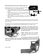
After connecting a power source to the ICRI (A), turn on the ICRI at (B) so that power up
and input voltage can be verified. If you need to use a DC source voltage between 6.5 and
7.4 volts, then neither the OK (C) nor the LOW (D) voltage LEDs will be lit, but the ICRI
will be working.
6.1.2.
Connect the radio interface cables to the ICRI. All five ICRI radio interface connections
(E1-5) are electrically identical, so it is not important which jacks are used during ICRI
operation.
6.1.3.
Connect the radio interface cables to the radios.
6.1.4.
Be sure the radios are on the channels assigned to the interoperability function.
6.1.5.
Select the talk-group the radio will be assigned to and place the switch above the associated
post in the designated position.
NOTE: The center position of the switch places any item connected with the associated port into a
“NO CONNECTION” conduction without physically disconnecting the device from the ICRI.
6.1.6.
Turn the radios on; initially place the radio volume controls at a mid-position between fully
counter-clockwise and fully clockwise. As a radio connected to the ICRI receives voice for a
remote radio user for the first time, adjust the radio’s volume control so that the associated
LED flickers as words are spoken. The LED should not remain on continuously as the voice
is received.
6.1.7.
Connect the telephone and handset, if they will be used.
NOTE: For initial setup and troubleshooting purposes, C-AT recommends the use of the local
handset or headset
6.1.8.
Select the talk-group the telephone and/or handset will be associated with.
6.1.9.
Turn on the telephone.
Содержание ICRI
Страница 13: ... 10 FIGURE 16 TWO RADIOS CONNECTED TO ICRI ...


