TECP-90-801 • Issue 4 • October 2017
Page 8
© 2017
CommScope
. All Rights Reserved.
3.1
Overview
Installation involves the following:
• Mounting the panel on a rack;
• Grounding the panel;
• Connecting the network control cable;
• Connecting power;
• Connecting the panel to the Quareo network;
• Installing controlled modules and cables.
3.2
Tools and Hardware Needed
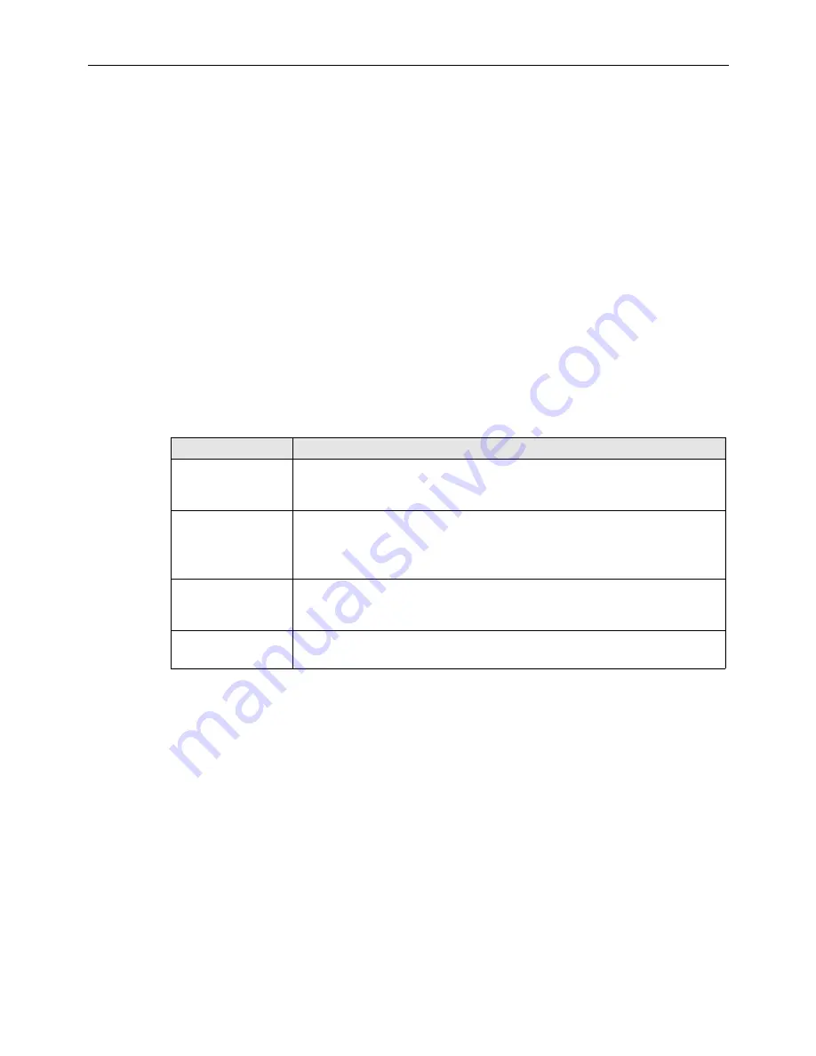
Tool and hardware requirements are listed in
.
Table 2. Installation Tools and Hardware Needs
CONSIDERATION
DESCRIPTION
Tools Needed
#1 Phillips Screwdriver,
#2 Phillips Screwdriver,
3/16” Standard Screwdriver
Rack Mounting
19” EIA/WECO/ETSI Rack Mounting. Use supplied #12-24 screws and #2
Phillips Screwdriver to secure the panel to the rack or cabinet or use supplied
M6 screws, cage nuts and #2 Phillips Screwdriver to secure the panel to the
rack or cabinet or use TrueNet
®
Frame “quick fit” solution
Grounding
Secure panel to ground. Use #1 Phillips Screwdriver to tighten the 10-32
screws through the ground lug (provided) into the panel ground PEM nuts.
Ground cables are NOT provided with the panel
Incoming IFC Cable
Clamping
Use supplied cable clamps and 3/16” standard screwdriver to secure the
incoming IFC cable
3.3
Rack Installation
The Quareo HDEP is shipped with extender brackets already attached for mounting the panel in
an ETSI equipment rack. The extender brackets may be removed for mounting the panel in a
19-inch (482.6mm) equipment rack. Mounting brackets for a 23-inch (58.42 cm) mounting are
supplied as ship along items.
Check the work order to determine the panel location in the rack or cabinet. Mounting hardware
is shipped loose. Each panel is secured with either 12-24 screws, M6 hardware, or TrueNet
®
quick fit hardware depending on type of mounting used.
Use the following procedure to mount the panel (refer to


