background image

M0201AA

ION

®

-E Series Hardware Installation Guide

© June 2017 CommScope, Inc.

Page 27

Installing Subracks and PSUs in an Equipment Rack

Install the CAN and TEN Cards

1

If necessary, remove the blank faceplate(s) from the slot(s) in which the DART is to be installed.

a

Loosen the two thumb screws that secure the blank faceplate(s) to the Host Unit chassis. 

b

Carefully withdraw the blank DART faceplate from the chassis.

c

Reserve the blank faceplates for future use.

2

Slide the card into the slot that it will occupy, and then push it back until its faceplate is flush against the 
subrack chassis.

3

Tighten the two thumbscrews that secure the card in the subrack chassis.

4

Do not leave any unoccupied slots open; replace blank faceplates, as necessary..

5

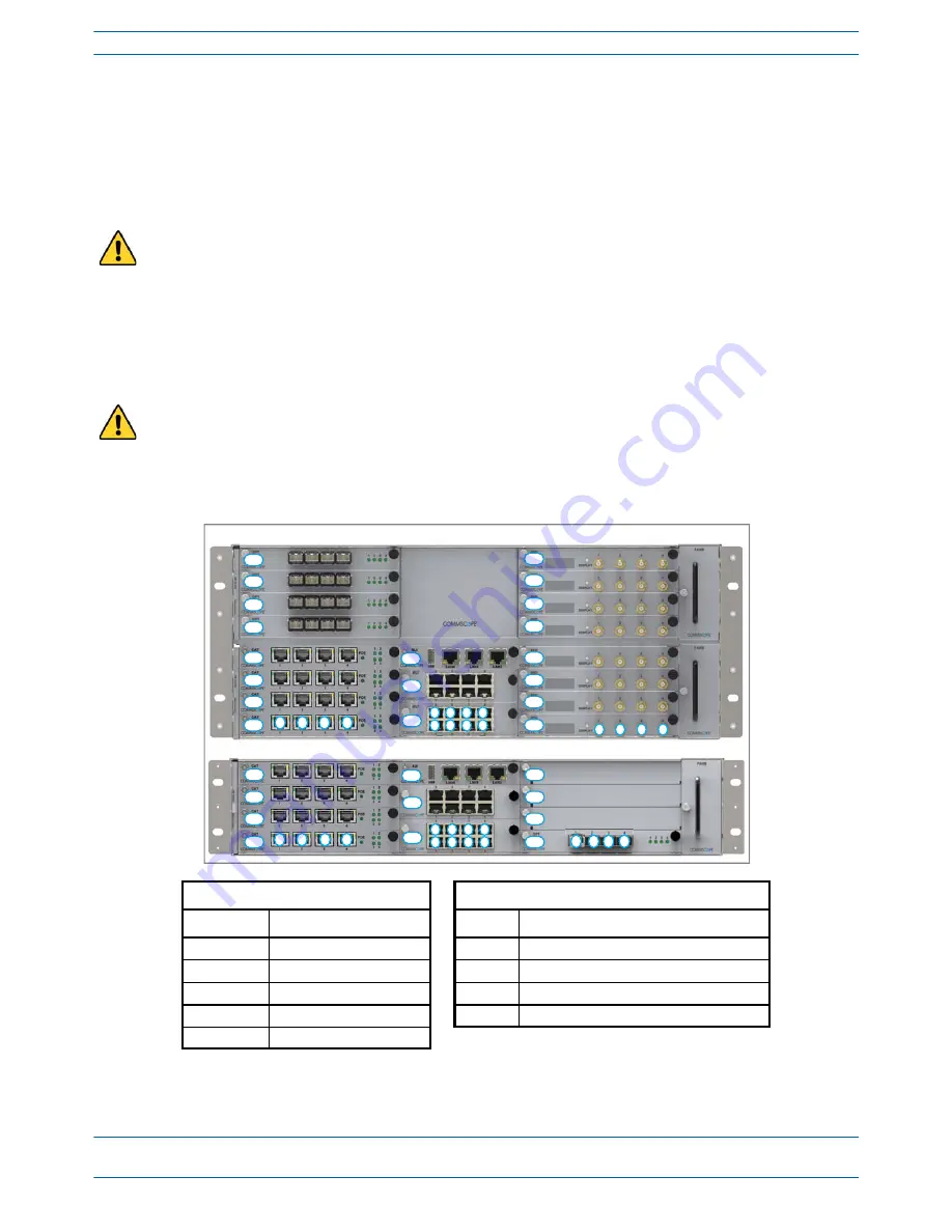
Follow the rules listed below to install the CAN and TEN cards into the WCS-2 or WCS-4 Subrack. 

Do not remove the blank faceplate from a slot in which a card will not be installed. To maximize airflow 
through the WCS chassis, blank panels must be installed in all empty Card slots. 

To maximize airflow through the WCS chassis, blank panels must be installed in all empty Card slots. If 
additional blank faceplates are required, you can order them from CommScope (see 

"Contacting DCCS 

Global Technical Support” on page 126

).

Placement of cards to create a CAN

Placement of cards to create a TEN 

2


Card Slot

Install this Card

Card Slot

Install this Card

L5 - L8

OPT Card

R1

OPT Card; use Port 1 to connect to the CAN

L1 - L4 

1


CAT Card

L1 - L4

CAT Card

R1 - R8

RFD Card

M3

SUI Card

M3

SUI Card

M1 - M2

AUT Card (optional)

M1 - M2

AUT Card (optional)

1

Can also be used for additional OPT 
Cards.

2

TENs do not support RFD Cards.

WCS-2 Subrack

L4

L3

L2

L1

M3

M2

M1

1

2

3

4

5

1

6

2

7

3

8

4

1

2

3

R4

R3

R2

R1

4

L4

L3

L2

L1

M3

M2

M1

WCS-4 Subrack

1

2

3

4

5

1

6

2

7

3

8

4

L8

L7

L6

L5

R8

R7

R6

R5

R4

R3

R2

R1

1

2

3

4

Содержание ION-E Series

Страница 1: ...ION E Series Hardware Installation Guide M0201AAA June 2017 ...

Страница 2: ...e reproduced stored in a retrieval system or transmitted in any form or by any means electronic mechanical photocopying recording or otherwise without the prior written permission of CommScope For patents see www cs pat com TRADEMARKS All trademarks identified by or are registered trademarks or trademarks respectively of CommScope Inc Names of other products mentioned herein are used for identific...

Страница 3: ...s 16 WCS Subrack Alarm Connector 17 WCS Fan Modules and Filters 18 System User Interface Card SUI 19 RF Donor Card RFD 20 Optical Transport Card OPT 21 Copper Transport Card CAT 22 Auxiliary Unit Transport Card AUT 23 Installing Subracks and PSUs in an Equipment Rack 24 Rack Mounting the Subracks and PSU 24 Connect the Subrack and PSU Power and Communication Cables 25 Install the CAN and TEN Cards...

Страница 4: ...ents 67 Cascading a UAP UAP X or UAP N25 68 UAP Maintenance 69 Remove a UAP from a Ceiling Mount 69 Remove a UAP from a Wall Mount 70 Preventative UAP Maintenance 71 UAP Specifications 72 UAP Output Specifications 72 UAP Bandwidth Specifications 73 7 Carrier Access Point Low Power CAP L ___________________________________________________________________75 Identifying CAP Ls in the ION E Software 7...

Страница 5: ...ptical Fiber Interface 111 Cable a CAP L with a Copper Interface and Power over Category 6A Cable 114 Cable a CAP L with a Copper Interface and Power over Ethernet 116 Cascading CAP Ls 118 CAP L Maintenance 119 Remove a CAP L from a Ceiling Mount 119 Remove a CAP L from a Wall Mount 120 Preventative CAP L Maintenance 121 CAP L Specifications 122 CAP L Output Specifications 122 CAP L Bandwidth Spec...

Страница 6: ...CPRI Digital Interface Unit Installation and Provisioning Guide M0201AAA Issue 1 Page vi June 2017 CommScope Inc Table of Contents ...

Страница 7: ...e June 2017 CommScope Inc Page 1 Chapter Topics Page Document Revision History 2 Document Cautions and Notes 3 Abbreviations Used in this Guide 4 This chapter provides information on how to use this hardware installation guide USING THIS DOCUMENT 1 ...

Страница 8: ...documentation hardware section of the ION E Series Software Version 2 0 0 User s Manual PN M0201A0D ION E Series Instructions for WCS Subracks PN M0201A1C ION E Series Instructions for Ceiling Mount UAP PN M0201A2A ION E Series Instructions for UAP Wall Mount PN M0201A3B ION E Series Instructions for UAP PN M0201A4A ION E Series Instructions for SUI RFD CAT OPT and AUT Cards PN M0201A5B ION E Seri...

Страница 9: ...icate a caution or warning Cautions and warnings indicate operations or steps that could cause personal injury induce a safety problem in a managed device destroy or corrupt information or interrupt or stop services The icon to the left indicates a caution or warning that pertains to laser equipment The icon to the left is indicates a caution or warning that pertains to Radio Frequency RF The icon...

Страница 10: ...t Number dBc Decibels referenced to the carrier PoCAT Power over Cate gory 6A cable dBm Decibel milliwatts PoE Power over Ethernet DC Direct Current POI Point of Interface EFTA European Free Trade Association RAN Regional Area Network EMC Electromagnetic Compatibility RF Radio Frequency EU European Union RFD RF Donor F Fahrenheit RTN Return FCC Federal Communications Commission RU Rack Unit Gb Gig...

Страница 11: ...are 9 Equipment Symbols with CE Compliance 9 Health and Safety Precautions 9 Property Damage Warnings 10 Compliance and Standards Certification 11 FCC RF Exposure Requirements 11 EMC Standards 11 FCC and IC Standards 12 This chapter provides information on the separate hardware components that an ION E Series system can comprise ION E SERIES HARDWARE OVERVIEW 2 ...

Страница 12: ...ss Point UAP connects the CAN TEN to an internal antenna receives data and power through Category 6A twisted pair cabling Supports Gigabit Ethernet for WiFi IP cameras or other devices in addition to wireless over a common cable UAP X connects the CAN TEN to an external antenna otherwise functions the same as the standard UAP Carrier Access Point Low Power CAP L interfaces with the CAN TEN via a C...

Страница 13: ...ocument guides you through the installation of a CommScope ION E system which supports the ION E system components identified in Table 2 1 on page 8 component graphics are not scaled to size For information on how to find the minimum software requirements for ION E hardware refer to Hardware to Software Mapping Information on page 129 ...

Страница 14: ...12 Vdc Module plugs into the Power Supply Subrack to provide 12 Vdc power to the WCS and e POI subracks 57 Vdc Power Module A 57 Vdc Module plugs into the Power Supply Subrack to provide remote power over Cat6A for the UAP and devices connected to the UAP UAP UAP N25 The Universal Access Point UAP which is connected to the ION E system via Cat6A cabling uses its internal antennas to transmit and r...

Страница 15: ... Alert sign to R TTE To be sold exclusively to mobile operators or authorized installers no harmonised frequency bands operation requires license Intended use EU and EFTA countries Indicates conformity with the R TTE directive 1999 5 EC certified by the notified body no 0700 A High leakage current ground earth connection to the Power Supply Subrack is essential before connecting the supply Laser r...

Страница 16: ...ogy to connect ESD protection measures Keep operating instructions within easy reach and make them available to all users Only license holders for the respective frequency range are allowed to operate this unit Read and obey all the warning labels attached to the unit Make sure that all warning labels are kept in a legible condition Replace any missing or damaged labels Make sure the unit s settin...

Страница 17: ...epeater and the antenna PD mW cm is the allowed Power Density limit acc to 47 CFR 1 1310 B for general population uncontrolled exposures which is f MHz 1500 for frequencies from 300MHz to 1500MHz 1 for frequencies from 1500MHz to 100 000MHz RF exposure compliance may need to be addressed at the time of licensing as required by the responsible FCC Bureau s including antenna co location requirements...

Страница 18: ...fe rence y compris les interfe rences qui peuvent causer un mauvais fonctionnement du dispositif Cet appareil est conforme avec Sante Canada Code de se curite 6 Le programme d installation de cet appareil doit s assurer que les rayonnements RF n est pas e mis au dela de I exigence de Sante Canada Les informations peuvent e tre obtenues http www hc sc gc ca ewh semt pubs radiation radio_guide ligne...

Страница 19: ...Optical Transport Card OPT 21 Copper Transport Card CAT 22 Auxiliary Unit Transport Card AUT 23 Installing Subracks and PSUs in an Equipment Rack 24 Rack Mounting the Subracks and PSU 24 Connect the Subrack and PSU Power and Communication Cables 25 Install the CAN and TEN Cards 27 Install SFP Transceivers in the OPT Cards 28 Connect the RFD Cards 29 Connect the CAT Cards 30 Connect the AUT Cards 3...

Страница 20: ...rea Nodes CAN or a Transport Expansion Nodes TEN The CAN is the server level control and primary signal distribution within an ION E system The TEN is the secondary distribution point that connects to a CAN using Multi Mode or Single Mode fiber The WCS 4 is four Rack Units RUs high and is typically used as a CAN but can also serve as a TEN The WCS 2 is two RUs high and is typically used as a TEN b...

Страница 21: ... have four ports L1 1 L1 2 L1 3 and L1 4 Install this Card in this Slot Optical Transport Card OPT CAT TEN L1 L8 R1 Copper Transport Card CAT L1 L4 1 System User Interface Card SUI M3 Auxiliary Unit Transport Card AUT M1 M2 RF Donor Card RFD CAT TEN R1 R8 N A 2 1 Remote Power for UAPs and CAP Ls over Cat6A only available in slots L1 L4 2 WCS Subracks configured as TENs do not currently support RFD...

Страница 22: ... This looks like it is the rear of the WCS 2 Are the connectors laid out the same on WCS 4 Ref Component Description 1 Rectifier Control connector 24 pin connector for PSU communication 2 POI connector POI Communication 3 POI Power connector 12 Vdc to e POI Subrack 4 Power connector Inputs to the 12 Vdc Module and the 57 Vdc Module 5 Alarm connector Dry contact input and output see WCS Subrack Ala...

Страница 23: ...solated chassis ground referenced dry contact inputs to monitor external devices one Summary Alarm Relay that energizes when specific alarms are triggered the thresholds of which are shown in the preceding graphic Which alarms We need to match the Summary Alarms shown above with the actual corresponding alarms NC COM NO ALARMS 1 2 3 4 5 6 Relay COM GND IN1 IN2 IN3 IN4 Relay NO Relay NC Summary Ala...

Страница 24: ...les apply to the WCS Fan Modules and Filters Fan Modules and Filters must be installed for WCS operation but they can be replaced without system interruption Filters are inserted on the left side of the WCS two filters are required for a WCS 4 Fan Modules are inserted on the right side of the WCS chassis two Fan Modules are required for a WCS 4 Filter Fan Module ...

Страница 25: ... link Green Link established with device to which the port is connected Flashing green Activity is occurring on that port Right Off 10 Mb connection established Yellow 100 Mb connection established SIU Card Connectors Ref Component Device Function 2 USB port 2 0 USB Connects to a a local laptop to allow the transfer of files 3 Local port Connects to a local laptop fixed IP address 4 LAN1 port RJ 4...

Страница 26: ...band The second line of the display shows the service provider or multiple if multiple providers are connected to the port 2 Display button Push button Push once to turn on the display backlight and then push four more times to cycle through the four ports 3 Port 1 1 Female QMA connector shown populated Connect to the UL DP Ports 1 4 on an e POI Module RF Paths simultaneous transmit and receive Pr...

Страница 27: ...ort for Multi Mode or Single Mode fiber Support for up to four SFP transceivers each SFP port provides high speed fiber connections between a CAN and a TEN OPT Card SFP Port LEDs 1 2 Ref LED LED Color Description 2 1 4 Off The OPT Card has no power or the OPT Card is plugged into the wrong subrack slot see WCS Subrack Front Panel Card Slots and GUI Identification on page 15 Green Optical link is e...

Страница 28: ...d 2 3 POE Off Power over Cat6A between the CAT Card and the UAP has not been established Green Power over Cat6A established between the CAT Card and the UAP 4 Port Off No power to the subrack Red Active fault on that link 1 Unless otherwise noted the use of UAP collectively refers to the UAP UAP X UAP N25 and the CAP L 2 1G link is not currently supported CAT Card Connectors Ref Component Device F...

Страница 29: ...bps can replace Gbit s and Mbps Mbit s For information on the internal mapping between CAT Cards and AUT Cards go to Connect the AUT Cards on page 32 AUT Card LEDs Ref LED LED Color Description 2 Left LED on RJ45 Ports 1 8 Off No activity on that port Flashing green Activity on that port Right LED on RJ45 Ports 1 8 Off Port is transmitting 1 Gbps Green Port is transmitting 100 Mbps or is not conne...

Страница 30: ...ion the following rules must be followed PSUs must be mounted above the WCS for support 1 RU of air space required above the PSU Support rails are required for WCS Subracks Support rails are required for e POI Subracks Support rails must not block airflow As with any piece of IT equipment placing the ION E system connection behind a secure firewall is highly recommended Disconnect all input to the...

Страница 31: ...Connect the Subrack and PSU Power and Communication Cables 1 Connect the rear panel power communication and control cables as shown in the following graphic e POI WCS PSU To From eNodeB e POI communica ons e POI power Subrack ground required WCS DC power Subrack ground required Rec fier control Subrack ground required 85 to 264 Vac ...

Страница 32: ... Plug the Rectifier Control Cable shown to the right into the WCS Rectifier Control connector press it in until you hear it click and lock into place e Plug the other end of the Rectifier Control Cable to the matching connector unlabeled on the rear of the PSU 3 Connect the Ground stud on the WCS PSU and e POI subracks to a suitable ground earth according to local and national electrical codes To ...

Страница 33: ... the WCS 2 or WCS 4 Subrack Do not remove the blank faceplate from a slot in which a card will not be installed To maximize airflow through the WCS chassis blank panels must be installed in all empty Card slots To maximize airflow through the WCS chassis blank panels must be installed in all empty Card slots If additional blank faceplates are required you can order them from CommScope see Contacti...

Страница 34: ...s L1 L8 TEN Slot R1 2 Use the system design to identify which OPT Card ports will be used in this system 3 Obtain the required number of SFP Transceivers 4 Slide the SFP into the OPT Card port identified in Step 2 and push the SFP into the Opt Card until you hear it click into place UNRESOLVED Connect to what R1 1 to CAN otherwise Cable Should you need to remove an SFP Transceiver press down on it...

Страница 35: ... Port 1 and Port 2 or to Port 3 and Port 4 3 If the signal levels of the BTS exceed the maximum input level of 27 dBm an e POI RF card or other suitable attenuator must be used to attenuate the signal For optimum PIM performance the composite level into a Donor RFD Card port should be less than 16 dBm If only one carrier is in a band PIM is probably not a concern For the case of two or more carrie...

Страница 36: ... ports 1 4 one per port Whether or not the UAP is cascaded determines how you connect the CAT Card to a UAP as described below Non Cascaded UAPS To connect up to four individual non cascaded UAPs to the CAT Card via ports 1 4 one per port UAP UAP N25 and UAP X connect the CAT Card port to the UAP Main port CAP L connect the CAT Card port to the CAP L Optical Port 1 An Ethernet device such as a cam...

Страница 37: ... one port unused UAP UAP N25 and UAP X connect the CAT Card port to the UAP Main port CAP L connect the CAT Card port to the CAP L Optical Port 2 Cascaded UAPs do not support Ethernet devices Other combinations of cascaded and non cascaded UAPs are also possible as long as the total number of UAPs connected to a CAT Card does not exceed six UAP UAP N25 UAP X CAT Ports 1 3 to from UAP Main port CAT...

Страница 38: ...s ready to use when the device is initially connected When an Ethernet device is connected to the AUX port of a UAP ION E detects the device re flashes the UAP to support the device and then reboots the UAP The UAP will perform the re flash and reboot process whenever the UAP or Ethernet device connected to the AUX port is changed The UAP s blue LED will blink while re flashing without interruptin...

Страница 39: ...evices connected to the Ethernet ports on the AUT Card Figure 3 3 Example of Internal Mapping of CAT Card Ports to AUT Ports Use the preceding information and the following steps to connect the AUT Card s to the ION E system 1 Follow the steps in Install the CAN and TEN Cards on page 27 to install the AUT Card s into the WCS Subrack Slots M1 M2 as needed for this CAT TEN installation 2 Refer to Fi...

Страница 40: ...ION E Series Hardware Installation Guide M0201AA Page 34 June 2017 CommScope Inc Installing Subracks and PSUs in an Equipment Rack ...

Страница 41: ...chapter provides a product overview and installation instructions for the ION E Series Point of Interface e POI Subracks UNRESOLVED The current e POI instruction sheet has 7 16 DIN connectors We need to update the instructions to the now0used 4 3 10 connectors Request for information out to Dieter Schiele who is out of the office until 3July17 UNRESOLVED Also not sure why the e POI was not include...

Страница 42: ...versal ION E Point Of Interface e POI Subrack provides power housing and communications for up to eight e POI RF Donor RFD Cards what does the e in e POI mean e POI Subrack Back Panel Connectors Interface Car IFC e Poi Subrack supports up to 8 RFD Cards Ground studs Communica on ports to WCS Subrack 12 Vdc Input connector from WCS Subrack 15A Blade Fuse ...

Страница 43: ...wever please verify that my correction above is correct IFC LEDs Ref LED LED Color Description 1 Status Off IFC not fully seated in slot or not receiving power Green IFC functioning to specification Red Active alarm on IFC 4 e POI Module Status 1 8 Off e POI Module in corresponding slot is not receiving power Green e POI Module in corresponding slot is functioningto specification RFD Card Status L...

Страница 44: ...ards Ref Component Device Function 1 UL DP Port 1 Female QMA connector Connect to the RFD Card Ports 1 4 2 UL DP Port 2 3 UL DP Port 3 4 UL DP Port 4 5 Module Power Com port 6 Ribbon cable 1 7 e Poi Subrack Power Com port 8 UL DL Ports 7 16 DIN connectors Connect to the eNodeB 1 The Ribbon cable is connected after the e POI Module is installed in the e POI Subrack 8 e Poi Module Back Panel e Poi M...

Страница 45: ...re Installation Guide June 2017 CommScope Inc Page 39 Installing an e POI Subracks and Modules INSTALLING AN E POI SUBRACKS AND MODULES UNRESOLVED I could not find any installation steps Emulate what was provided for WCS subracks ...

Страница 46: ... 1 Disconnect the Ribbon cable from the e POI Module that you are removing from the e POI Subrack 2 Loosen the two thumbscrews on the bottom of the e POI Module and pull it from the subrack 3 Press the Config button on the IFC for 5 seconds This tells the ION E Software to scan and delete the removed e POI Module from inventory and clear any alarms related to that e POI Module 4 Wait for the e POI...

Страница 47: ...ation Notes Height x width x depth mm 4U x 19 x 395 Weight kg 7 7 Operating temperature C 5 to 50 Support rails are required for rack mounting Table 4 2 e POI Module Specifications Parameter Specification Notes Operational frequency MHz 300 to 2700 Attenuation dB 30 2 698 2700 MHz 35 5 3 5 380 450 MHz 33 5 3 2 450 698 MHz RF input power 46 dBm PIM 2x20 Watts 3rd order 153 dBc Input voltage Vdc Pow...

Страница 48: ...ION E Series Hardware Installation Guide M0201AA Page 42 June 2017 CommScope Inc e POI Subrack and Component Specifications ...

Страница 49: ...apter Topics Page Power Supply Unit PSU 44 PSU Modules and Connectors 44 12 Vdc Power Module LEDs 45 57 Vdc Power Module LEDs 46 Installing PSUs 47 This chapter provides a product overview and installation instructions for the ION E Series Power Supply Unit PSU POWER SUPPLY UNIT PSU 5 ...

Страница 50: ...er terminal Provides the connection point for the RTN Negative Black Wire 5 AC Input IEC 60320 C19 Power connector Provides the connection point for the for 57V module Slot 4 6 AC Input IEC 60320 C19 Power connector Provides the connection point for the for 57V module Slot 3 7 Rectifier control connector 24 pin terminal block Provides the connection point for the to the WCS 8 AC Input IEC 60320 C1...

Страница 51: ... 2 DC Green DC output is within the specified range 3 FLT Fault Red There is no AC input or a failure has been detected in the 12 Vdc Power Module The Fault LED activates under the following conditions If two 12 Vdc Power Modules are installed in the PSU and the AC input is removed cable unplugged from one of the modules If only one 12 Vdc Power Module is installed in the PSU and AC power is remov...

Страница 52: ... On On On Off Defective fan blown AC fuse in Power Module boost stage failure over voltage latched shutdown On Off Off On No AC 15 mS single unit Off On Off Off AC present but not within limits Blinks Off Off Off AC not present Off Off Off Off Over current On Blinks Off Off Non catastrophic internal failure any detectable fault that does not shut down the unit On On Off On Communications fault RS4...

Страница 53: ...A ION E Series Hardware Installation Guide June 2017 CommScope Inc Page 47 Installing PSUs INSTALLING PSUS UNRESOLVED I could not find any installation steps UNRESOLVED Do we have any power consumption specs ...

Страница 54: ...ION E Series Hardware Installation Guide M0201AA Page 48 June 2017 CommScope Inc Installing PSUs ...

Страница 55: ... 00 63 Required Tools for a Wall Mount 63 Unpack and Inspect the Wall Mounting Kit 64 Mount the UAP to a Wall 64 UAP UAP N25 and UAP X Cable Requirements 67 Cascading a UAP UAP X or UAP N25 68 UAP Maintenance 69 Remove a UAP from a Ceiling Mount 69 Remove a UAP from a Wall Mount 70 Preventative UAP Maintenance 71 UAP Specifications 72 UAP Output Specifications 72 UAP Bandwidth Specifications 73 Th...

Страница 56: ...g UAP X Units in the ION E Software Table 6 1 UAP Identification in the ION E Software WCS Slot CAT Port Primary UAP Direct Connect Secondary UAP AUX Port Connect WCS Slot CAT Port Primary UAP Direct Connect Secondary UAP AUX Port Connect L1 1 UAP L1 1a UAP L1 1b L5 1 UAP L5 1a UAP L5 1b L1 2 UAP L1 2a UAP L1 2b L5 2 UAP L5 2a UAP L5 2b L1 3 UAP L1 3a UAP L1 3b L5 3 UAP L5 3a UAP L5 3b L1 4 UAP L1...

Страница 57: ...n port RJ45 connector Provides data and power to UAP over Cat6A 2 AUX port RJ45 connector Provides data and power to 2nd UAP or Ethernet devices 3 Power button Pushbutton switch Turns power to UAP on off Power to the UAP may also be shutdown via the ION E Series Software CAUTION Prior to disconnecting a Cat6A cable from the UAP press the red Power button to power off the UAP UAP Status LED unlabel...

Страница 58: ...devices 5 Power button Pushbutton switch Turns power to UAP on off Power to the UAP may also be shutdown via the ION E Series Software CAUTION Prior to disconnecting a Cat6A cable from the UAP X press the red Power button to power off the UAP X UAP X Status LED unlabeled Ref LED Color Description 6 Blue UAP is transmitting as expected Fast flash blue Unit Identifier activated in the ION E GUI for ...

Страница 59: ...found or parts are missing file a claim with the commercial carrier and notify CommScope Technical Support see Contacting DCCS Global Technical Support on page 126 Save the damaged cartons for inspection by the carrier 4 Save all shipping containers for use if the equipment requires shipment at a future date Unless otherwise noted the use of UAP in the Universal Access Point installation procedure...

Страница 60: ...on of the UAP X above the ceiling is desired it is the installer s responsibility to confirm that the installation complies with all local and national electrical safety and fire codes In addition if the UAP X is mounted above the ceiling the installer must ensure that sufficient space is maintained around the UAP X for adequate cooling Care must be taken when positioning the antennas connected to...

Страница 61: ...op of the UAP so that the screw holes and cable cutouts align properly 4 Place the ceiling tile over the shroud with the finished surface of the ceiling tile facing downward 5 Place the two part sliding support bar on top of the shroud and align it with the center of the UAP 6 Place mounting bracket over the sliding support bar and align it with the threaded mounting holes in the UAP Sliding Moun ...

Страница 62: ...grid and make sure that the support bar clips are attached to the ceiling grid 11 Connect the Cat6A cables to the Main and AUX ports of the UAP Grounding is not mandatory UAPs are classified as low voltage devices and do not have internal power supplies However CommScope recommends you check local and national electrical codes to determine if grounding is a requirement for the location in which yo...

Страница 63: ... standard 60 cm x 60 cm 2 x2 suspended ceiling grid If the grid uses 120 cm x 60 cm 4 x2 ceiling tiles add an additional cross runner cross tee to the main runner to support the unit A minimum overhead clearance of 70 cm is recommended UAP wall mounting kit 7683181 00 is also available from CommScope for mounting a UAP to a wall or hard ceiling Required Tools for a Quick Release Ceiling Mount Kit ...

Страница 64: ...nstalled in a standard 60 cm x 60 cm 2 x 2 suspended ceiling grid If the grid uses 120 cm x 60 cm 4 x 2 ceiling tiles add an additional cross runner cross tee to the main runner to support the unit A minimum overhead clearance of 70 cm is recommended as shown below Table 6 3 Quick Release Ceiling Mount Kit PN 00 Quantity Component Description Quantity Component Description 1 Template 1 each Left a...

Отзывы:

Похожие инструкции для ION-E Series