7
HOMEDEPOT.COM
Please contact 1-877-527-0313 for further assistance.
Operation (continued)
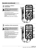
2
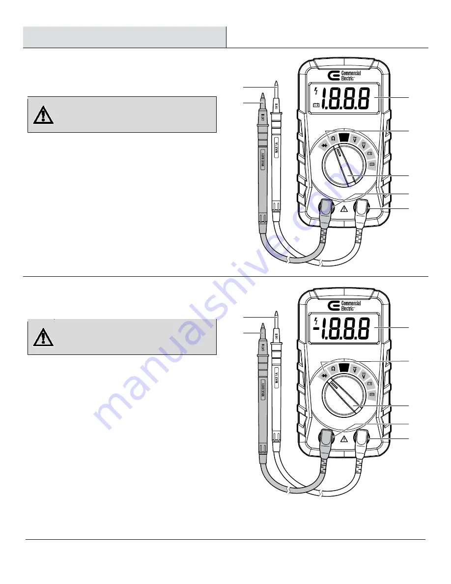
Completing a resistance
measurement
WARNING:
To avoid damage to the meter or equipment
being measured, cut off all power supply to the measured
circuits and discharge all high voltage capacitors before
measuring resistance.
□
Set the switch (B) to the
Ω position (1)
.
□
Connect the black test lead (F) to the common jack (C) and
the red test lead (E) to the positive jack (D).
□
Connect the test leads (E and F) to the circuit being
measured.
□
Read the measured resistance value on the display (A).
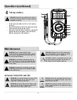
3
Completing a diode measurement
WARNING:
To avoid damage to the meter or equipment
being measured, cut off all power supply to the measured
circuits and discharge all high voltage capacitors before
measuring diode.
□
Set the switch (B) to the
diode position (1)
.
□
Connect the black test lead (F) to the common jack (C) and
the red test lead (E) to the positive jack (D).
□
Separately connect the black test lead (F) and the red test
lead (E) to the negative pole and positive pole of the
measured diode.
□
The display (A) shows the forward bias value of the
measured diode. If the poles of the test leads are
connected inversely, the meter displays “OL”.
DIGITAL MULTIMETER
MS8132A
300VCATIII
1.5V
9V
OFF
2K
B
A
C
D
1
F
E
DIGITAL MULTIMETER
MS8132A
300VCATIII
1.5V
9V
OFF
2K
B
A
C
D
1
F
E


