


LS-37B User’s Manual
-28-
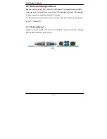
2.11 <Serial Port>
The board supports one RS232 serial port and one jumper selectable RS232/422/485 serial
ports. The jumper JCSEL1 & JCSEL2 can let you configure the communicating modes for
COM2.
Connector:
COM1
Type: 9-pin D-sub male connector on bracket for COM1
Pin
Description
Pin
Description
1 DCD
2 RXD
3 TXD
4 DTR
5 GND
6 DSR
7 RTS
8 CTS
9 RI
10
N/C
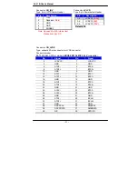
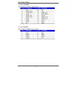
Connector:
COM2
Type: 10-pin (5 x 2) 1.27mm x 2.54mm-pitch header for COM2
Pin
Description
Pin
Description
1 DCD/422TX-/485- 2 RXD/422TX+/485+
3 TXD/422RX+
4 DTR/422RX-
5 GND
6 DSR
7 RTS
8 CTS
9 RI
10
N/C
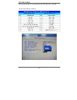
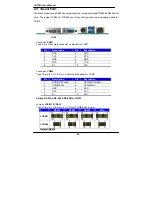
Setting RS-232 & RS-422 & RS-485 for COM2
Jumper:
JCSEL1,JCSEL2
Type: 12-pin (6 x 2) & 8-pin (4 x 2) for set COM2 mode jumper
RS232
RS485
RS422
IrDA
JCSEL1
JCSEL2
Default: RS232
COM1