background image

507868-02P

Page 41 of 48

Issue 1922

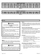
Testing for Proper Venting and Sufficient Combustion Air for Non-Direct Vent Applications

CARBON MONOXIDE POISONING HAZARD

Failure  to  follow  the  steps  outlined  below  for  each 

appliance  connected  to  the  venting  system  being 

placed into operation could result in carbon monoxide 

poisoning or death.
The following steps shall be followed for each appliance 

connected  to  the  venting  system  being  placed  into 

operation, while all other appliances connected to the 

venting system are not in operation.

 WARNING

After  the  gas  furnace  has  been  started,  the  following 

test  should  be  conducted  to  ensure  proper  venting  and 

sufficient combustion air has been provided to the unit as 

well as to other gas fired appliances which are separately 

vented.

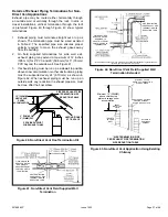
If  this  furnace  replaces  a  Category  I  furnace  which  was 

commonly  vented  with  another  gas  appliance,  the  size 

of  the  existing  vent  pipe  for  that  gas  appliance  must  be 

checked.  Without  the  heat  of  the  original  furnace  flue 

products, the existing vent pipe is probably oversized for 

the single water heater or other appliance. The vent should 

be checked for proper draw with the remaining appliance.

The test should be conducted while all appliances (both 

in operation and those not in operation) are connected to 

the venting system being tested. If the venting system has 

been installed improperly, or if provisions have not been 

made for sufficient amounts of combustion air, corrections 

must be made as outlined in the previous section.

1.  Seal any unused openings in the venting system.
2.  Visually  inspect  the  venting  system  for  proper  size 

and horizontal pitch. Determine there is no blockage 

or restriction, leakage, corrosion, or other deficiencies 

which could cause an unsafe condition.

3.  To the extent that it is practical, close all building doors 

and  windows  and  all  doors  between  the  space  in 

which the appliances connected to the venting system 

are located and other spaces of the building. 

4.  Close fireplace dampers.
5.  Turn  on  clothes  dryers  and  any  appliances  not 

connected to the venting system. Turn on any exhaust 

fans, such as range hoods and bathroom exhausts, so 

they will operate at maximum speed. Do not operate a 

summer exhaust fan. 

6.  Follow the lighting instruction to place the appliance 

being inspected into operation. Adjust thermostat so 

appliance will operate continuously.

7.  Use the flame of a match or candle to test for spillage 

of flue gases at the draft hood relief opening after 5 

minutes of main burner operation. 

8.  If  improper  venting  is  observed  during  any  of  the 

above tests, the venting system must be corrected or 

sufficient  combustion/makeup  air  must  be  provided. 

The venting system should be resized to approach the 

minimum size as determined by using the appropriate 

tables in appendix G in the current standards of the 

National Fuel Gas Code ANSI-Z223.1/NPFA 54 in the 

U.S.A., and the appropriate Natural Gas and Propane 

appliances venting sizing tables in the current standard 

of the CSA-B149 Natural Gas and Propane Installation 

Codes in Canada.

9.  After  determining  that  each  appliance  remaining 

connected  to  the  common  venting  system  properly 

vents when tested as indicated in step 3, return doors, 

windows,  exhaust  fans,  fireplace  dampers  and  any 

other gas burning appliance to their previous condition 

of use.

Содержание GDD92C

Страница 1: ...or loss of life Installation and service must be performed by a licensed professional installer or equivalent service agency or the gas supplier WARNING As with any mechanical equipment personal injur...

Страница 2: ...507868 02P Page 2 of 48 Issue 1922 Unit Dimensions Capacity A B C in mm in mm in mm 045 B3 070 B3 17 1 2 446 16 3 8 416 16 406 090 C4 21 533 19 7 8 504 19 1 2 495...

Страница 3: ...Heating Compartment Access Panel Blower Access Panel Cold End Header Box Control Box includes integrated control transformer and door switch Blower Assembly Bag Assemblies Cabinet Blower Deck Heat Ex...

Страница 4: ...aded street elbow Check equipment for shipping damage If you find any damage immediately contact the last carrier Please refer to specification sheets for available accessories Safety Information DANG...

Страница 5: ...must be equipped to prevent operation of either the heating or the cooling unit unless it is in the full HEAT or COOL setting When installed this furnace must be electrically grounded according to lo...

Страница 6: ...re drafts might blow directly into it This could cause improper combustion and unsafe operation When the furnace is installed in a non direct vent applications do not block the furnace combustion air...

Страница 7: ...ombustion and ventilation depend largely on whether the furnace is installed in an unconfined or a confined space Unconfined Space An unconfined space is an area such as a basement or large equipment...

Страница 8: ...n of rectangular air ducts shall be no less than 3 inches 75 mm In calculating free area the blocking effect of louvers grilles or screens must be considered If the design and free area of protective...

Страница 9: ...ined Space all Air from Outside Shipping Bolt Removal Units with 1 2 hp and 3 4 hp blower motors are equipped with three flexible legs and one rigid leg The rigid leg is equipped with a shipping bolt...

Страница 10: ...Do not drag the unit across the floor in the downflow position Floor and furnace flange damage will result Refer to Figure 14 for clearances in downflow applications Improper installation of the furna...

Страница 11: ...2 After opening is cut set the combustible flooring base into opening 3 Check fiberglass strips on the combustible flooring base to make sure they are properly glued and positioned 4 Lower supply air...

Страница 12: ...external static pressure which exceeds 0 5 inches w c Operation at these conditions may result in improper limit operation Supply Air Plenum If the furnace is installed without a cooling coil a remov...

Страница 13: ...ces of ignition Do not use excessive amounts of solvent cement when making joints Good ventilation should be maintained to reduce fire hazard and to minimize breathing of solvent vapors Avoid contact...

Страница 14: ...s Termination kits 44W92 and 44W93 are approved for use in Canadian installations to meet CSAB149 The 44W92 Concentric kit is provided with a 1 1 2 accelerator which must be installed on the exhaust o...

Страница 15: ...condition 3 Close all building doors and windows and all doors between the space in which the appliances remaining connected to the common venting system are located and other spaces of the building...

Страница 16: ...om outdoors and flue gases are discharged outdoors Intake and exhaust pipe sizing Size pipe according to Table 6 and Table 7A through Table 7B Table 6 lists the minimum vent pipe lengths permitted Tab...

Страница 17: ...13 97 97 78 8 26 11 60 45 n a 92 92 73 9 21 n a 55 40 87 87 68 10 16 50 35 82 82 63 Concentric Termination Elevation 0 10 000 ft Number of 90 Elbows Used 1 1 2 Pipe 2 Pipe 2 1 2 Pipe 3 Pipe Model Mode...

Страница 18: ...60 67 67 48 10 6 40 55 62 62 43 NOTE Additional vent pipe and elbows used to terminate the vent pipe outside the structure must be included in the total vent length calculation Figure 23 Typical Exhau...

Страница 19: ...the furnace from the surrounding space the indoor air quality must be considered Guidelines listed in Combustion Dilution and Ventilation Air section must be followed Follow the next two steps when i...

Страница 20: ...r to Outside Roof Terminated Exhaust Pipe Furnace Ventilation Louvers Crawl Space Intake Debris Screen Provided Inlet Air Minimum 12 in 305mm above Crawl Space Floor Coupling or 3 in to 2 in Transitio...

Страница 21: ...n in Unconditioned Space for Winter Design Temperatures Single Stage High Efficiency Furnace Winter Design Temperatures1 F C Vent Pipe Diameter Unit Input Size 045 070 090 32 to 21 0 to 6 PVC 2 PP PVC...

Страница 22: ...ce under veranda porch deck or balcony 12 Equal to or greater than soffit depth 3 feet 9m 12 3 feet 9m within a height 15 feet 4 5m above the meter regulator assembly 3 feet 9m 6 inches 152mm for appl...

Страница 23: ...mm for appliances 10 000 pliances 10 000 Btuh 3kw and 50 000 pliances 50 000 Btuh 15kw 6 inches 152mm for appliances 10 000 Btuh 3kw 12 inches 305mm for appliances 10 000 Btuh 3kw and 100 000 Btuh 30k...

Страница 24: ...tion is 3 76 mm on roof terminations and 6 152 mm on side wall terminations 3 On roof terminations the intake piping should terminate straight down using two 90 elbows see Figure 31 4 Exhaust piping m...

Страница 25: ...t Furnished CLAMP INTAKE 12 305mm FIELD PROVIDED REDUCER MAY BE REQUIRED TO ADAPT DIFFERENT VENT PIPE SIZE TO TERMINATION Figure 36 Direct Vent Concentric Wall Termination DIRECT VENT CONCENTRIC WALL...

Страница 26: ...n tee should be connected to the 2 or 3 PVC flue pipe as shown in the illustration Do not use an accelerator in applications that include an exhaust termination tee The accelerator is not required 2 A...

Страница 27: ...pipe size must be done after the final elbow Figure 40 Non Direct Vent Roof Termination Kit UNCONDITIONED ATTIC SPACE 3 76MM OR 2 51MM PVC PROVIDE SUPPORT FOR EXHAUST LINES 12 305MM ABOVE AVE SNOW ACC...

Страница 28: ...ermination Drain Trap assembled Figure 44 Kit 51W18 USA 15Z70 Canada Parts Identification and Assembly Exhaust from Furnace To Termination Exhaust from Furnace To Termination Kit 51W18 is shown Figure...

Страница 29: ...ondensate drain Tubing must be 1 1 4 ODx1 ID and should be attached to the drain on the trap using a hose clamp Figure 47 Condensate Trap and Plug Locations 5 Figure 49 shows the furnace and evaporato...

Страница 30: ...507868 02P Page 30 of 48 Issue 1922 Figure 49 Evaporator Coil Using a Separate Drain Figure 50 Evaporator Coil Using a Common Drain Figure 51 Condensate Trap with Optional Overflow Switch...

Страница 31: ...507868 02P Page 31 of 48 Issue 1922 Figure 52 Trap Drain Assembly Using 1 2 PVC or 3 4 PVC...

Страница 32: ...ip leg in vertical pipe runs to serve as a trap for sediment or condensate 5 A 1 8 N P T plugged tap or pressure post is located on the gas valve to facilitate test gauge connection See Figure 53 6 In...

Страница 33: ...4 118 3 34 110 3 11 103 2 92 1 25 4 1 049 26 645 680 19 25 465 13 17 375 10 62 320 9 06 285 8 07 260 7 36 240 6 80 220 6 23 205 5 80 195 5 52 1 1 4 31 75 1 380 35 052 1400 39 64 950 26 90 770 21 80 66...

Страница 34: ...long enough to facilitate future removal of blower for service Complete the wiring connections to the equipment Use the provided unit wiring diagram and the field wiring diagram shown in Figure 58 Us...

Страница 35: ...ly on the heating speed when there is no cooling or heating demand See Table 16 for allowable continuous circulation speeds 2 When the furnace is running in the heating mode the indoor blower will run...

Страница 36: ...507868 02P Page 36 of 48 Issue 1922 045B3 070B3 090C4 Figure 59 Typical Wiring Diagram...

Страница 37: ...next to the floor because some gas is heavier than air and will settle on the floor The gas valve on the unit is equipped with a gas control switch lever Use only your hand to move switch Never use to...

Страница 38: ...low the gas supplier s instructions If you do not smell gas go to next step 8 Move gas valve switch to ON See Figure 61 9 Replace the heating compartment access panel 10 Turn on all electrical power t...

Страница 39: ...rt unit and allow 5 minutes for unit to reach steady state 3 While waiting for the unit to stabilize observe the flame Flame should be stable and should not lift from burner Natural gas should burn bl...

Страница 40: ...Orifice Kit All 11K50 73W80 51W01 11K45 Conversion requires installation of a gas valve regulator spring which is provided with the gas conversion Kit LP Kits include low line pressure switch Pressur...

Страница 41: ...2 Visually inspect the venting system for proper size and horizontal pitch Determine there is no blockage or restriction leakage corrosion or other deficiencies which could cause an unsafe condition 3...

Страница 42: ...nticipator setting if adjustable according to the amp draw listed on the wiring diagram that is attached to the unit Electrical 1 Check all wiring for loose connections 2 Check for the correct voltage...

Страница 43: ...65 276 1140 202 860 109 700 73 0 20 1345 360 1240 285 1090 208 810 119 645 79 0 30 1325 371 1215 291 1060 218 770 124 590 84 0 40 1295 380 1175 302 1025 228 710 132 530 91 0 50 1260 392 1135 318 985 2...

Страница 44: ...nsure proper furnace operation Table 3 lists recommended filter sizes Exhaust and Air Intake Pipes Check the exhaust and air intake pipes and all connections for tightness and to make sure there is no...

Страница 45: ...abinet Remove two screws from blower rail which secure bottom heat exchanger flange Remove heat exchanger from furnace cabinet 17 Back wash heat exchanger with soapy water solution or steam If steam i...

Страница 46: ...ent will be displayed first LED off for 3 sec then next error code is displayed etc To clear error codes depress and hold button longer than 5 seconds Cleaning the Burner Assembly 1 Turn off electrica...

Страница 47: ...blems detected during the inspection may make it necessary to temporarily shut down the furnace until the items can be repaired or replaced Instruct the homeowners to pay attention to their furnace Si...

Страница 48: ...height of eight 8 feet above grade directly in line with the exhaust vent terminal for the horizontally vented gas fueled heating appliance or equipment The sign shall read in print size no less than...

Отзывы: