background image

Service Manual  -  

DVC 09/12/18/24 SF Series

34

39

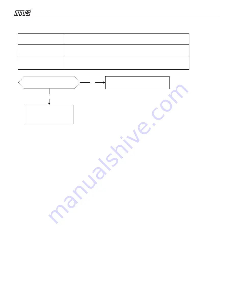
8.2.3 Zero crossing detection error diagnosis and solution (E2)

Error Code

E2

Malfunction conditions  When PCB does not receive zero crossing signal feedback for 4 

minutes or the zero crossing signal time interval is abnormal.

Possible

 causes

Connection

error

PCB faulty

Troubleshooting:

Check if the connections and 

power supply 

are

 normal?

Correct the connections. Turn on the 

unit when the power supply is good.

No

Yes

Indoor main PCB is 

defective. Replace indoor 

main PCB.

Содержание A-DVC09SF-0

Страница 1: ...www marsdelivers com Service Manual DVC Series Inverter Single Zone Ductless Mini Split A DVC09SF 0 A DVC12SF 0 A DVC18SF 1 A DVC24SF 1 B DVC09SF 0 B DVC12SF 0 B DVC18SF 1 B DVC24SF 1 ...

Страница 2: ...e cables 15 5 3 Pipe length and the elevation 16 5 4 Installation for the first time 17 5 5 Adding refrigerant after the system has been in service 17 5 6 Re installation after indoor unit repairs 18 5 7 Re installation after outdoor unit repairs 18 6 Operation Characteristics 20 7 Electronic function 21 7 1 Abbreviation 21 7 2 Display function 21 7 3 Main Protection 22 7 4 Operation Modes and Fun...

Страница 3: ...duct Sharp edges could cause injury be especially careful of the case edges and the fins on the condenser and evaporator For installation always contact the dealer or an authorized service center Do not install the product on a defective installation stand Be sure the installation area does not deteriorate with age If the base collapses the air conditioner could fall with it causing property damag...

Страница 4: ...ct Low refrigerant levels may cause failure of product Install the drain hose to ensure that water is drained away properly A bad connection may cause water leakage Keep level even when installing the product It can avoid vibration or water leakage Do not install the product where the noise or hot air from the outdoor unit could disturb the neighborhood It may cause a problem for your neighbors Us...

Страница 5: ...sonal injury Replace the all batteries in the remote control with new ones of the same type Do not mix old and new batteries or different types of batteries There is risk of fire or explosion Do not recharge or disassemble the batteries Do not dispose of batteries in a fire They may burn or explode If the liquid from the batteries gets onto your skin or clothes wash it well with clean water Do not...

Страница 6: ... 18 24 SF Series 6 4 2 Model List Model Names of Indoor Outdoor Units Inverter Capacity Indoor units Outdoor units 9K B DVC09SF 0 A DVC09SF 0 12K 18K 24K B DVC12SF 0 A DVC12SF 0 B DVC18SF 1 B DVC24SF 1 A DVC18SF 1 A DVC24SF 1 ...

Страница 7: ... 18 24 SF Series 7 5 3 Dimensions 3 1 Indoor Unit Model W D H B DVC09SF 0 722 28 43 187 7 36 290 11 42 B DVC12SF 0 B DVC18SF 1 B DVC24SF 1 802 31 57 189 7 44 297 11 69 965 37 99 215 8 46 319 12 56 1080 42 52 226 8 9 335 13 19 ...

Страница 8: ...Service Manual DVC 09 12 18 24 SF Series 8 6 For B DVC09SF 0 For B DVC12SF 0 For B DVC18SF 1 ...

Страница 9: ...Service Manual DVC 09 12 18 24 SF Series 9 7 For B DVC24SF 1 ...

Страница 10: ...Service Manual DVC 09 12 18 24 SF Series 10 8 3 2 Outdoor Unit More than 30cm 11 81 More than 60cm 23 62 More than 200cm 78 74 More than 30cm 11 81 More than 60cm 23 62 Service space Fence or obstacles ...

Страница 11: ...18 24 SF Series 11 9 For A DVC09SF 0 A DVC12SF 0 487 19 17 W1 70 2 76 W2 298 11 73 555 21 85 300 11 81 D H 12 60 2 36 93 3 66 H1 H2 D1 770 80 31 W 779 30 67 W3 322 12 68 D2 25 98 B1 90 B2 61 5 2 42 A2 12 47 A1 R 6 286 11 26 D3 ...

Страница 12: ...24 SF Series 12 10 For A DVC18SF 1 800 31 5 W 514 20 24 W1 554 21 81 60 2 36 85 5 3 37 340 13 39 12 0 47 311 12 24 815 32 09 W3 365 14 37 333 13 11 D 70 2 76 W2 H H1 H2 D1 D2 D3 62 2 44 B1 106 4 17 B2 20 79 A1 R20 R6 61 6 2 43 A2 ...

Страница 13: ...Service Manual DVC 09 12 18 24 SF Series 13 For A DVC24SF 1 ...

Страница 14: ...Service Manual DVC 09 12 18 24 SF Series 14 4 Refrigerant Cycle Diagram ...

Страница 15: ...gf cm 4700 479kgf cm Ф19 3 4 6500 663kgf cm 6700 683kgf cm 5 2 Connecting the cables The power cord of connect should be selected according to the following specifications sheet Rated current of appliance Nominal cross sectional area mm 3 and 6 0 75 6 and 10 1 10 and 16 1 5 16 and 25 2 5 The cable size and the current of the fuse or switch are determined by the maximum current indicated on the nam...

Страница 16: ...as Liquid DVC09SF 0 3 8 Ф9 52 1 4 Ф6 35 7 5 10 25 15 DVC12SF 0 DVC18SF 1 DVC24SF 1 1 2 Ф12 7 1 4 Ф6 35 7 5 10 25 15 7 5 10 25 15 5 8 Ф15 9 3 8 Ф9 52 7 5 20 30 30 Caution The capacity test is based on the standard length and the maximum permissive length is based on the system reliability 25 ft 32 ft 82 ft 16 oz ft 25 ft 32 ft 82 ft 25 ft 64 ft 98 ft 1 2 Ф12 7 1 4 Ф6 35 16 oz ft 16 oz ft 323 oz ft ...

Страница 17: ...ose with the push pin of low pressure handle to the 3 way valves gas service port 3 Connect the charge hose of high pressure handle connection to the vacuum pump 4 Fully open the low pressure handle of the manifold valve 5 Operate the vacuum pump to evacuate 6 Evacuate for 30 minutes and check whether the compound meter indicates 300 microns If the meter does not indicate 300 microns after pumping...

Страница 18: ...ighten the service port cap to a torque of 18N m Be sure to check for gas leakage 5 6 Re installation after indoor unit repairs 1 Collecting the refrigerant into the outdoor unit Procedure 1 Confirm that both the 2 way and 3 way valves are set to the opened position Remove the valve stem caps and confirm that the valve stems are in the opened position Be sure to use a hexagonal wrench to operate t...

Страница 19: ...he charge hose Open the valve at the bottom of the cylinder and press the check valve on the charge set to purge the air be careful of the liquid refrigerant 3 Put the charging cylinder onto the electronic scale and record the weight 4 Open the valves Low side on the charge set and charge the system with liquid refrigerant If the system cannot be charged with the specified amount of refrigerant or...

Страница 20: ...CAUTION 1 If the air conditioner is used beyond the above conditions certain safety protection features may come into operation and cause the unit to operate abnormally 2 The room relative humidity should be less than 80 If the air conditioner operates beyond this figure the surface of the air conditioner may attract condensation Please set the vertical air flow louver to its maximum angle vertica...

Страница 21: ... room temperature in FAN mode Displays the self diagnostic codes Displays for three seconds when Timer ON Fresh Swing Turbo or Silence feature is activated Displays for three seconds when Fresh Swing Turbo or Silence feature is cancelled Displays during defrosting operation Displays when anti cold air feature is activated during heating mode Displays during self clean operation if applicable Displ...

Страница 22: ...temperature 3 C the preheating function will be activated 7 3 8 Sensor protection at open circuit and breaking disconnection When there s only one temperature sensor in malfunction the air conditioner will keep working but show the error code in case of any emergency use When there s more than one temperature sensor in malfunction the air conditioner will stop working 7 3 9 Refrigerant leakage det...

Страница 23: ... different fan speed according to T4 For different outdoor units the fan speeds are different For DVC09SF 0 DVC12SF 0 DVC18SF 1 DVC24SF 1 High Low 7 4 2 3 Indoor fan running rules In cooling mode indoor fan runs all the time and the speed can be selected as high medium low and auto The indoor fan is controlled as below Td Ts Δt The auto fan acts as below rules a b c d T1 TS e Setting fan speed Act...

Страница 24: ... machine will turn on automatically when reaching the setting time 7 4 7 3 Timer off The machine will turn off automatically when reaching the setting time 7 4 7 4 Timer on off The machine will turn on automatically when reaching the setting on time and then turn off automatically when reaching the setting off time 7 4 7 5 Timer off on The machine will turn off automatically when reaching the sett...

Страница 25: ...oor PCB receives the signal which results from pressing the FOLLOW ME button on remote controller the buzzer will emit a sound and this indicates the follow me function is initiated But when the indoor PCB receives signal which sent from remote controller every 3 minutes the buzzer will not respond When the unit is running with follow me function the PCB will control the unit according to the temp...

Страница 26: ...splaying code Meaning T1 T1 Indoor room temp T2 T2 Indoor coil mid temp T3 T3 Outdoor coil temp T4 T4 Outdoor temp T2B Tb Indoor coil outlet temp TP TP Compressor discharge temp TH TH IPM modular temp Targeted Frequency FT Targeted Frequency Actual Frequency Fr Actual Frequency Indoor fan speed IF Indoor fan speed Outdoor fan speed OF Outdoor fan speed EXV opening angle LA EXV opening angle Compre...

Страница 27: ...1 129 d0 d1 d9 130 131 139 E0 E1 E9 140 141 149 F0 F1 F9 150 151 159 Indoor fan speed Outdoor fan speed 0 OFF 1 2 3 4 Low speed Medium speed High speed Turbo For some big capacity motors 14 FF Actual fan speed Display value turns to decimal value and then multiply 10 The unit is RPM For some small capacity motors display value is from 14 FF hexadecimal the corresponding fan speed range is from 200...

Страница 28: ...orget to discharge the electricity in capacitor Electrolytic Capacitors HIGH VOLTAGE CAUTION For other models please connect discharge resistance approx 100Ω 40W or soldering iron plug between terminals of the electrolytic capacitor on the contrary side of the outdoor PCB Note The picture above is only for reference The plug of your side may be different ...

Страница 29: ...or short circuit 5 times O F4 Outdoor unit EEPROM parameter error 6 times O F5 Outdoor fan speed has been out of control 1 times P0 IPM malfunction or IGBT over strong current protection 2 times P1 Over voltage or over low voltage protection 3 times P2 High temperature protection of IPM module or compressor top diagnosis and solution 4 times P3 Outdoor ambient temperature too low 5 times P4 Invert...

Страница 30: ...C 09 12 18 24 SF Series 30 35 Troubleshooting Use the remote controller If the unit does not respond to the remote the indoor PCB needs to be replaced if the unit does respond then the display board needs to be replaced ...

Страница 31: ...Possible causes Installation error PCB faulty Troubleshooting Yes Replace the indoor outdoor main PCB Power off then restart the unit 2 minutes later Does it run EEPROM a read only memory whose contents can be erased and reprogrammed using a pulsed voltage For the location of EEPROM chip please refer to the below photos Indoor PCB Outdoor PCB Note The two photos above are only for reference it s m...

Страница 32: ...faulty Troubleshooting Yes No Yes No No Yes No Yes No Power off then restart the unit 2 minutes later Is the error extinguished Measure Vs Is the voltage moving alternately between 25V to 25V Replace the reactor Check the indoor wiring connection Is the wiring correct Check the outdoor wiring connection Is the wiring correct Replace the indoor main PCB Power on Is the error extinguished Is the rea...

Страница 33: ...al 3 S When AC is normal running the voltage will move alternately between 25V to 25V If the outdoor unit has malfunction the voltage will move alternately with positive value If the indoor unit has malfunction the voltage will be a steady value Remark Use a multimeter to test the resistance of the reactor which does not connect with capacitor The normal value should be around zero ohm Otherwise t...

Страница 34: ...oes not receive zero crossing signal feedback for 4 minutes or the zero crossing signal time interval is abnormal Possible causes Connection error PCB faulty Troubleshooting Check if the connections and power supply are normal Correct the connections Turn on the unit when the power supply is good No Yes Indoor main PCB is defective Replace indoor main PCB ...

Страница 35: ...ulty Troubleshooting Shut off the power supply and turn it on 2 minutes later Is it still displaying the error code Shut off the power supply rotate the fan by hand Does it rotate properly The unit operates normally Find the cause and repair For example check whether the fan is blocked or the bearing is broken Check the wires of fan motor Are all the connections good No Yes No Correct the connecti...

Страница 36: ... NO Color Signal Voltage 1 Red Vs Vm 140V 190V 2 3 Black GND 0V 4 White Vcc 14 17 5V 5 Yellow Vsp 0 5 6V 6 Blue FG 14 17 5V 2 Outdoor DC Fan Motor control chip is in outdoor PCB Power on and check if the fan can run normally if the fan can run normally the PCB must be replaced If the fan does not run normally measure the resistance between each two pins If the resistance is not equal between all p...

Страница 37: ...ling voltage is lower than 0 06V or higher than 4 94V the LED will display the failure Possible causes Wiring error Sensor faulty PCB faulty Troubleshooting Check the connections between temperature sensor and main PCB Are the connections good Correct the connections No Yes Yes Replace indoor or outdoor main PCB Replace the sensor Check the resistance value of the sensor is it normal No ...

Страница 38: ...ossible causes T2 sensor faulty Indoor PCB faulty System problems such as leakage or blocking Troubleshooting Is there cool air blowing out from indoor air outlet Yes Yes Check T2 sensor connection Correct the installation or replace T2 sensor Does the problem remain No Is there any leakage Especially the connection parts such as the gas valve and the liquid valve No Shut off the power supply and ...

Страница 39: ...faulty Wiring error Compressor malfunction Troubleshooting Check the power supply Is it normal Check the connections and wires Is it well connected Stop the unit Check the power supply No Yes No Correct the connections or replace the wires Yes Replace the outdoor main PCB Yes Check the reactor Is it normal No Replace the reactor Is there any blockage No Yes Clear the blockage Check the compressor ...

Страница 40: ...Check the wiring between main PCB and compressor Are the wires or connectors broken Correct the connection or replace the wires and connectors Yes No IPM continuity check Are the IPM terminal resistance values uniform Replace the IPM board or replace the main PCB if the IPM board and main PCB are integrated together No Check if the outdoor fan runs properly or the outdoor unit ventilation is good ...

Страница 41: ...Service Manual DVC 09 12 18 24 SF Series 41 For example P U P V Note The photos below are only for reference it s may be not same totally with the ones on your side ...

Страница 42: ...Service Manual DVC 09 12 18 24 SF Series 42 47 P W N U ...

Страница 43: ...Service Manual DVC 09 12 18 24 SF Series 43 48 N V N W ...

Страница 44: ...sible causes Power supply problems System leakage or blockage PCB faulty Troubleshooting Check the power supply Check the connections and wires Stop the unit Not within parameters OK Bad Correct the connections or replace the wires OK Replace the reactor Bad Bad Replace the IPM board Check the voltage between P and N Check the reactor OK OK Replace outdoor main PCB Remark Measure the DC voltage be...

Страница 45: ...of indoor and outdoor units are obstructed Clear up the air inlet and outlet or the heat exchanger of indoor and outdoor units Yes No Yes Yes Turn off the power supply and turn it on 10 minutes later Check if the temperature of compressor top is more than 194 F No Check if the refrigerant system is normal Repair the refrigerant system Replace the outdoor control PCB Yes Check if all the connection...

Страница 46: ...essor connected well Correct the connection or replace the wires and connectors No Is the IPM installed correctly Correct the installation tighten the screws and apply silicon grease No IPM continuity check Are the IPM terminal resistance values uniform Yes Replace the IPM board or replace the main PCB if the IPM board and main PCB are integrated together No Check if the outdoor fan runs properly ...

Страница 47: ...rge capacity electrolytic capacitors discharge completely and dismount the IPM Use a digital tester to measure the resistance between P and UVWN UVW and N Digital tester Normal resistance value Digital tester Normal resistance value Red Black Several MΩ Red Black Several MΩ P N U N U V V W W Red ...

Страница 48: ...P6 Error Code P6 Malfunction conditions When the pressure of system reach a certain value the low pressure protector will switch off After the pressure resume to normal the protection code will disappear Possible causes Wiring error Pressure protector faulty Fan motor faulty PCB faulty System problems ...

Страница 49: ...the temperature sensor from PCB measure the resistance value with a tester Temperature Sensors Room temp T1 sensor Indoor coil temp T2 sensor Outdoor coil temp T3 sensor Outdoor ambient temp T4 sensor Compressor discharge temp TP sensor Measure the resistance value of each winding by using the multi meter ...

Страница 50: ...37 99 5 87359 77 171 1 29078 117 243 0 38991 2 28 38 8239 38 100 5 62961 78 172 1 25423 118 244 0 37956 1 30 37 1988 39 102 5 39689 79 174 1 2133 119 246 0 36954 0 32 35 2024 40 104 5 17519 80 176 1 17393 120 248 0 35982 1 34 33 3269 41 106 4 96392 81 178 1 13604 121 250 0 35042 2 36 31 5635 42 108 4 76253 82 180 1 09958 122 252 0 3413 3 37 28 9058 43 109 4 5705 83 181 1 06448 123 253 0 33246 4 39...

Страница 51: ...8 75 167 8 084 115 239 2 422 4 25 222 8 36 97 34 32 76 169 7 82 116 241 2 357 3 27 211 4 37 99 32 94 77 171 7 566 117 243 2 294 2 28 200 7 38 100 31 62 78 172 7 321 118 244 2 233 1 30 190 5 39 102 30 36 79 174 7 086 119 246 2 174 0 32 180 9 40 104 28 15 80 176 6 859 120 248 2 117 1 34 171 9 41 106 28 81 178 6 641 121 250 2 061 2 36 163 3 42 108 26 9 82 180 6 43 122 252 2 007 3 37 155 2 43 109 25 8...

Страница 52: ...3 145 4 94 201 2 125 257 4 38 2 33 91 4 64 147 2 95 203 126 258 8 4 5 40 1 34 93 2 65 149 96 204 8 127 260 6 5 41 35 95 66 150 8 97 206 6 128 262 4 6 42 8 36 96 8 67 152 6 98 208 4 129 264 2 7 44 6 37 98 6 68 154 4 99 210 2 130 266 8 46 4 38 100 4 69 156 2 100 212 131 267 8 9 48 2 39 102 2 70 158 101 213 8 132 268 6 10 50 40 104 71 158 8 102 215 6 133 271 4 11 51 8 41 105 8 72 161 6 103 217 4 134 ...

Страница 53: ...60 Appendix 4 Normal voltage of P and N 208 240V 1 phase 3 phase 380 420V 3 phase In standby around 310VDC around 530VDC In operation With passive PFC module With partial active PFC module With fully active PFC module 200VDC 310VDC 370VDC 450VDC ...

Страница 54: ...SF Series 54 2 Compressor checking Measure the resistance value of each winding by using the tester Position Resistance Value ASN98D22UFZ ASM135D23UFZ ATF235D22UMT ATF250D22UMT Blue Red 1 75 Ω 0 75 Ω 0 75 Ω Blue Black Red Blue 1 57Ω ...

Страница 55: ...Service Manual DVC 09 12 18 24 SF Series 55 This page intentionally left blank ...

Страница 56: ...GDWD RQ WKH DFWXDO SURGXFW SULRU WR EHJLQQLQJ DQ LQVWDOODWLRQ SUHSDUDWLRQV QFHQWLYH DQG UHEDWH SURJUDPV KDYH SUHFLVH UHTXLUHPHQWV DV WR SURGXFW SHUIRUPDQFH DQG FHUWLILFDWLRQ OO SURGXFWV PHHW DSSOLFDEOH UHJXODWLRQV LQ HIIHFW RQ GDWH RI PDQXIDFWXUH KRZHYHU FHUWLILFDWLRQV DUH QRW QHFHVVDULO JUDQWHG IRU WKH OLIH RI D SURGXFW 7KHUHIRUH LW LV WKH UHVSRQVLELOLW RI WKH DSSOLFDQW WR GHWHUPLQH ZKHWKHU D VSH...

Отзывы: