Comelit HFX-700M Скачать руководство пользователя страница 9

Operat es t he sam e as t he m ain m onit or unit  (Ref er t o page 4).

6

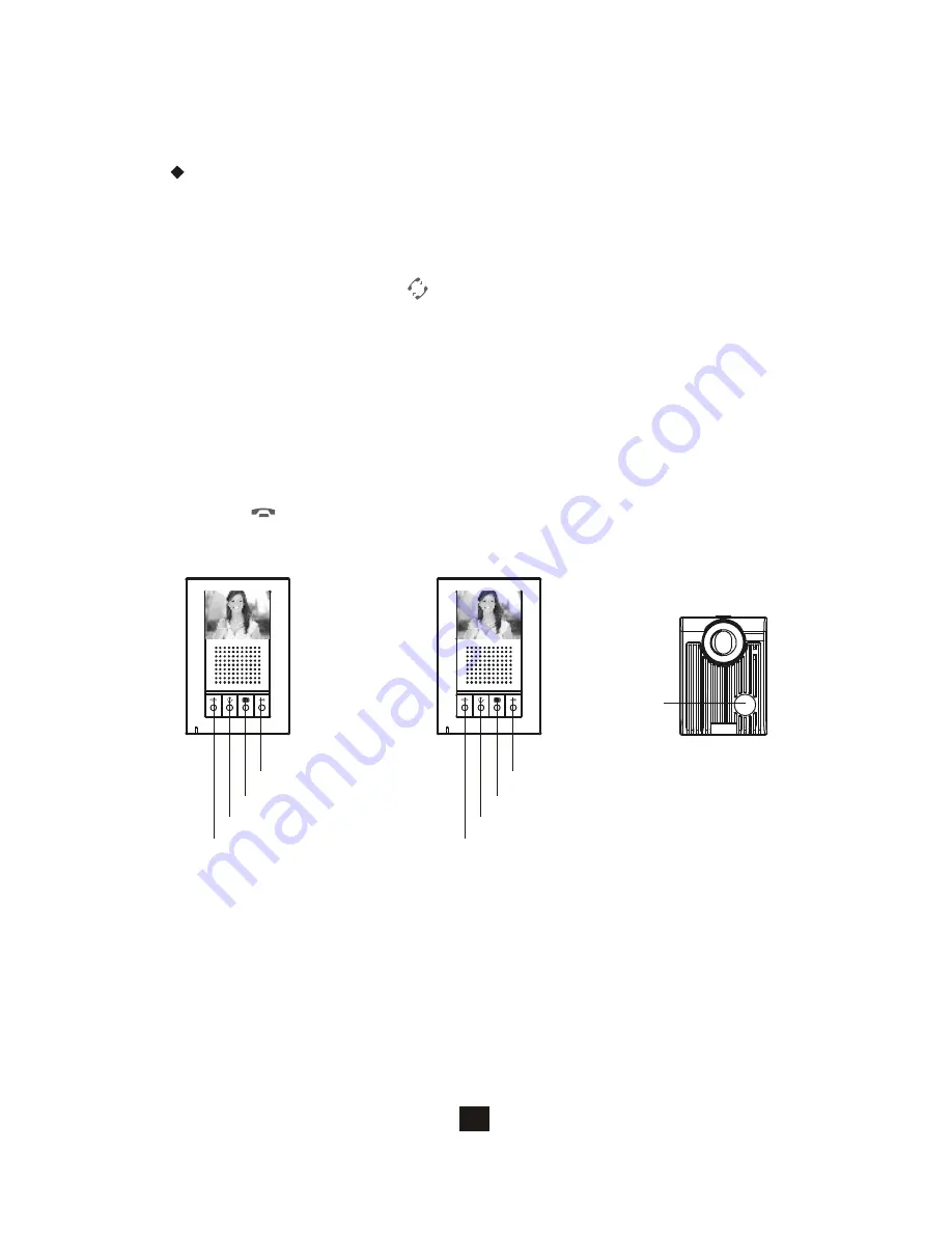
3.2. EX-700H Oper at i on

Mai n m oni tor

Door cam era

Call butt on

Cut-off but ton

Int ercom  butt on

Monitoring butt on

Door release butt on

3.2.1.Br oadcast  and  i nt er com  f u nct ion

A. When syst em  consist s of  m ain m onit or and ex pansion monit or and an 
    out door doorbell/ cam era unit , t he syst em can provide int ercom  funct ion.
B. Press the intercom  but t on      from  any m onitor, all ot her m onit ors will 
    react by m aking bell sound. At t he sam e t ime, host can speak and 
    broadcast voice m essage t o all other m onit ors.
C. The broadcast  m ode can last  f or 20 seconds. During t he 20 seconds, 
    any ot her m onitor can answer t he call by having t he intercom  but t on 
    pressed in order t o engage t he int ercom  com m unication. Once t he 
    int ercom com municat ion has been est ablished, t alk t im e is f or a 
    m ax im um  of 90 seconds. This f unct ion provides audio int ercom 
    com m unicat ion only, m onitors will not show any video.
D. At  anyt im e if  you wish t o t erminat e t he m onit oring, press the Cut -of f
    but ton       t o t erminat e t he syst em .

Ex pansion m onit or

Cut-off but ton

Int ercom  butt on

Monit oring but ton

Door release butt on

Содержание HFX-700M

Страница 1: ...HANDS FREE EXPANDABLE VIDEO INTERCOM SYSTEM OWNER S MANUAL INSTALLATION AND OPERATION HFX 700M KIT...

Страница 2: ...or camera 2 2 2 Audio and video monitoring 2 2 3 3 Expansion video monitor EX 700H 3 1 EX 700H Identification 3 2 EX 700H Operation 3 2 1 Broadcast and intercom function Expansion audio monitor EX 700...

Страница 3: ...5 4 1 JP2 6 Expansion door camera EX 700D installation 6 1 Examine package contents 6 2 Install expansion door camera 6 3 EX 700D wiring and setting 7 Metal door camera housing EX 700V installation 7...

Страница 4: ...room in your home or office Visitors activate the system by pressing a call button on the outdoor camera which sounds a doorbell chime as well as turning on the inside video monitor A two way intercom...

Страница 5: ...tuner 14 Sharpness tuner 15 Bell Volume tuner 16 Speaker Volume tuner 17 18 19 Communication LED JP1 video display option during door release operation Enable video display JP1 left default Disable v...

Страница 6: ...onitor 10 11 CCD vertical view angle adjustment dial JP 2 automatic LED light supplement option JP1 lock control output option and CCD on off during the output 98mm 3 86 2 3 5 4 6 1 3 JP1 JP2 1 2 3 4...

Страница 7: ...voice broadcast 2 2 2 Audio and Video monitoring A Pressing the monitor button will turn on the audio and video from door camera B If there is a second door camera on this system pressing the Monitor...

Страница 8: ...9 Intercom button 10 Monitoring button 11 Door release button 12 Power switch 13 Brightness tuner 14 Sharpness tuner 15 Bell Volume tuner 16 Speaker Volume tuner 17 18 Communication LED JP1 video disp...

Страница 9: ...ll sound At the same time host can speak and broadcast voice message to all other monitors C The broadcast mode can last for 20 seconds During the 20 seconds any other monitor can answer the call by h...

Страница 10: ...ff button 8 Intercom button 9 Monitoring button 10 Door release button 11 Power switch 12 Bell Volume tuner 13 Speaker Volume tuner 14 Communication LED JP2 door status report option Bell tone indicat...

Страница 11: ...other monitors will react by making bell sound At the same time host can speak and broadcast voice message to all other monitors C The broadcast mode can last for 20 seconds During the 20 seconds any...

Страница 12: ...5 2 EX VIN Operation 1 AA EX VIN converts video signal on the 2 wire transmission format of the system B Press the monitor button from any monitor to see the camera from the main door camera press it...

Страница 13: ...gnal wires Signal wires Wire assignment AWG 22 parallel wires AWG 18 parallel wires Wire type CAT 5 AWG 24 A Max B Max 100 m 3 28 f eet 100 m 3 28 f eet 100 m 3 28 f eet 100 m 3 28 f eet 100 m 3 28 f...

Страница 14: ...amplify and distribute the 2 wire signal among the main monitor and sub monitors NOTE 2 the system is capable of expanding up to a total of 5 monitors with 1 EX HUB or 8 total monitors with 2 EX HUBs...

Страница 15: ...ER IN OUT1 OUT2 OUT3 OUT4 EX HUB EX 700H or EX 700A EX 700H or EX 700A NOTE 1 OUT4 can also be used to connect to a ex pansion monitor NOTE 2 wiring distance 300ft C Max POWER LED POWER IN OUT1 OUT2 O...

Страница 16: ...monitor to door camera Maximum of 328 feet with AWG18 normal 2 wire parallel wires or CAT 5 cable From monitor to monitor every section Maximum of 328 feet with AWG22normal 2 wire parallel wires or CA...

Страница 17: ...monitor Do not plug in the pow er at this stage Wall mount bracket Monitor 3 HFX 700M installation 3 1 Examine package contents Door camera X1 X1 Main monitor X1 Wall mount bracket PT1 PT2 DG1 DG2 OU...

Страница 18: ...JP1 JP2 1 2 3 4 Main monitor Wiring terminal Red Black 1 2 4 5 door camera Wiring terminal 3 6 7 8 9 3 4 HFX 700M wiring and setting A Wire the system from terminal to terminal accordingly 1 2 3 4 5...

Страница 19: ...e to the equipment B DG1 and DG2 have polarity C JP3 on left for N O dry contact default allow bypass current of 24VDC 1A figure 1 D JP3 on right for 12VDC150mA current output figure 2 A Enable video...

Страница 20: ...2 Using pow er from the system Electric Lock Power for Lock Door camera 12 24V DC 1 Amp Max Electric Lock JP1 JP2 1 2 3 4 Door camera Figure 1 Figure 2 JP1 3 6 Jumper function on door camera 3 6 1 JP1...

Страница 21: ...to 4 3 C Select jumpers for desired function Refer to 4 4 D Plug in pin wires and mount the monitor unit on bracket 4 2 Install expansion video monitor Do not plug power at this stage Wall mount brack...

Страница 22: ...2 IN IN OUT OUT POWER Expansion monitor wiring terminal Red Black To next expansion monitor 3 4 5 Magnetic switch 2 3 4 5 4 4 Jumper function on EX 700H 19 JP1 JP2 4 4 2 JP2 door status report options...

Страница 23: ...monitor unit on bracket 20 5 2 Install expansion audio monitor Do not plug pow er at this stage Wall mount bracket Monitor 5 Expansion audio m onit or EX 700A Inst allat ion 5 1 Exam ine pack age cont...

Страница 24: ...w polarity Terminals for power adapter Connect to a N C magnetic switch sensor for door status detection 1 2 PT1 PT2 IN IN OUT OUT POWER Expansion monitor wiring terminal Red Black To next expansion m...

Страница 25: ...ill be installed C Fasten wires on terminals and select jumpers for desired function page 17 D Mount door camera unit back on the bracket and secure the assembly screw Door camera Bracket Pull out scr...

Страница 26: ...wall cut open size Front panel outlook 100x150x41 114x165x49 120x180x7 Unit mm Unit inch 3 94 x5 91 x1 62 4 49 x6 50 x1 93 4 72 x7 08 x0 28 A Examine the following contents of the package B EX 700V i...

Страница 27: ...2 directly on the wooden wall A Install bracket 1 on top of bracket 2 A Remove doorbell camera unit from its plastic wall mount bracket B Install the doorbell camera unit on top of bracket 1 A Place r...

Страница 28: ...Optional video input converter EX VIN Installation 8 1 Install video input converter A Package contains no accessories B Wire EX VIN to the video distribution box of the camera C Plug in BNC no settin...

Страница 29: ...ting 7 8W maximum Image Sensor Resolution Camera Lens View Angle Auto Light Sensor Operating Temperature Dimensions w bracket Power consumption Remote Control dry contact bridge Remote Control direct...

Страница 30: ...ions w bracket Power adaptor Power consumption 30 seconds time out 90 seconds for conversation 20 seconds time out 90 seconds for conversation 14 F 140 F indoor 4 65 L x 7 0 W x 1 42 D input 100 240VA...

Страница 31: ...eck to ensure polarity is correct Red positive Black negative System is on but no picture on the monitor Make sure the cable is cnnected securely between the master monitor and the camera Adjust the b...

Страница 32: ...titute risk of electrical shock to persons The exclamation point within an equilateral triangle is intended to alert the user to the presence of important operating and maintenance servicing instructi...

Страница 33: ...where they exit the equipment Cleaning Clean the equipment by wiping with a soft cloth do not use any abrasive agents or water Non use Periods Power cords should be unplugged from the outlet when lef...

Страница 34: ...ce pursuant to Part 15 of the FCC rules These limits are designed to provide reasonable protection against harmful interference in a residential installation This equipment generates uses and can radi...

Страница 35: ...nty is good for one year from the date purchased If the product reacts down under proper treatment during warranty please contact our after sales connection for free of charge repairs c The following...

Страница 36: ...ht t p w w w com elitusa com Inf o com elitusa com...

Отзывы: