


IPC98
Network Camera Module
w/ remote snap shot
4
Chapter 2: Hardware Installation
2.1
Hardware and Connection Description
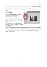
Figure1: Main Board Layout
2.2 Hardware Installation
1
. plug the Ethernet cable into the LAN port as figure 1 show
2
. plug the other end of the Ethernet cable into available LAN connection devices, such as Hub, Router,
ADSL modem and so on.
3.
plug in power connector, you will see status LED blinking three times, then off. It is now initializing
the system,(probably 5 seconds)
。
If success, status LED will flash once per second
Please make sure that you use the right power adapter of 5VDC output for IP camera, using a
non-approved power will damage the camera.
SD Card holder
(Option)
RJ45 – connect to LAN
Power – DC5V
Reset
Status LED
To Sensor Board