background image


www.combisteel.com 

Basic Parameters 

Model 

7455.0450 


7455.0455 

Voltage 

220~240V 

50/60Hz 

220~240V 

50/60Hz 

220~240V 

50/60Hz 

220~240V 

50/60Hz 

220~240V 

50/60Hz 

Power 

1.8KW 

1.8KW 

1.8KW 

1.8KW 

2.2KW 

Temperature 

controller number 

Temperature 

range 

50~300


50~300


50~300


50~300


50~300


Upper grill size 

214×214(mm) 

214×214(mm) 

214×214(mm) 

214×214(mm) 

340×220(mm) 

Lower grill size 

218×230(mm) 

218×230(mm) 

218×230(mm) 

218×230(mm) 

340×230(mm) 

Dimension 

290×395×210(mm) 

430×395×210(mm) 


Model 

7455.0460 


Voltage 

220~240V 

50/60Hz 

220~240V 

50/60Hz 

220~240V 

50/60Hz 

220~240V 

50/60Hz 

220~240V 

50/60Hz 

Power 

3.6KW 

3.6KW 

3.6KW 

3.6KW 

4.4KW 

Temperature 

controller number 

Temperature 

range 

50~300


50~300


50~300


50~300


50~300


Upper grill size 

214×214(mm) 

214×214(mm) 

214×214(mm) 

214×214(mm) 

340×220(mm) 

Lower grill size 

475×230(mm) 

475×230(mm) 

475×230(mm) 

475×230(mm) 

720×230(mm) 

Dimension 

570×395×210(mm) 

810×395×210(mm) 


Transportation and Storage 

Please handle the grill carefully and cautiously during transportation and do not turn it upside down to prevent 
any damage to the shell and interior. The packed grill should be stored in the storehouse that’s well ventilated 
and non-corrosive. Any waterproof measures should be taken during temporary storage. 


Notes 


The working voltage of the equipment should match that of the power supply. 


Suitable switch, fuse breaker and three-phase socket should be installed near the equipment. 


There is an earth bolt at the back of the equipment. Please connect the earth wire in compliance with 
the safety regulations reliably with copper cable of no less than 2mm. 


Before using, user should check whether connection is firm, voltage is regular and earth connection is 
safe. 


Do not put any object onto the upper module plate and shake the lift operation handle with sudden 
force. 


Cut off power supply while cleaning. Do not use wet towel with corrosive cleanser and do not directly 
splash water on the equipment. 


The  adjustable  temperature  of  the  equipment  is  between  50~200

.  It  is  recommended  that  the 

maximum working temperature should normally be 200~250


Do not store any flammable objects near the equipment. The environment temperature should be lower 
than 45

, the humidity is under 85%. 


The installation and maintenance of the equipment should be done by professional technicians. 


Содержание 7455.0450

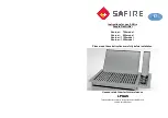
Страница 1: ...Contact Grill 7455 0450 7455 0455 7455 0460 User Manual Gebruikershandleiding Gebrauchsanweisung Le mode d emploi...

Страница 2: ...onmaak en onderhoud 14 Probleemoplossing 14 Dagelijkse controle 14 Detailzicht 15 DEUTSCH Au enkonstruktion 18 Funktionsumfang und struktur 18 Grundparameter 19 Transport und Lagerung 19 Betriebsanlei...

Страница 3: ...re reference Warning Any refitting and wrong installation adjustment and maintenance can lead to property loss and casualty Please contact the supplier if user needs adjustments which should be done b...

Страница 4: ...SWITCH 4 BOTTOM BOX 5 OIL TRAY 6 LOWER MODULE PLATE 7 FEED WIRE TUBE 8 UPPER MODULE PLATE 9 OPERATION HANDEL 10 POWER CORD 11 RUBBER FEET 1 HEATING INDICATOR 2 TEMEPRATURE CONTROLLER 3 POWER SWITCH 4...

Страница 5: ...age to the shell and interior The packed grill should be stored in the storehouse that s well ventilated and non corrosive Any waterproof measures should be taken during temporary storage Notes The wo...

Страница 6: ...n the socket and turn on the power Turn the temperature controller clockwise to the temperature needed The yellow indicator is on to show that the heating wire begins to heat and the upper and lower g...

Страница 7: ...led 1 Temperature controller is out of order 1 Change temperature controller 3 Indicator is not on when the power is on and the heating process is normal 1 Indicator is broken 1 Change temperature con...

Страница 8: ...8 www combisteel com K Solid Resolution Graph Declaration The upper and lower module plate of 7455 0450 and 7455 0455 are ribbed Declaration The upper and lower module plate 7455 0460 are ribbed...

Страница 9: ...ULE 25 PLATEN OF UPPER ELECTRIC HEATING TUBE 26 GRILL OF UPPER MODULE 27 ELECTRIC HEATING TUBE OF UPPER MODULE 28 INCOMING LINE TUBE 29 SPRING CHECK RING FOR AXLE 30 SPRING CHECK RING FOR TUBE 31 AXLE...

Страница 10: ...foutieve installatie of onderhoud kan leiden tot malfunctie van het apparaat en verwondingen Gelieve contact op te nemen met de fabrikant als er aanpassingen dienen te gebeuren aan het apparaat Elke...

Страница 11: ...rkten etc Opbouw buitenkant 1 INDICATIELAMPJE 2 TEMPERATUURREGELAAR 3 AAN UITKNOP 4 ONDERSTE MODULE 5 OLIEOPVANGRESERVOIR 6 ONDERSTE MODULE PLAAT 7 STROOMKABEL 8 BOVENSTE MODULE PLAAT 9 HANDVAT 10 STR...

Страница 12: ...grill moet worden bewaard in een goed geventileerde ruimte en uit de buurt van elke soort corrosieve stoffen Bij tijdelijke opslag moet hij bewaard blijven uit de wind en regen Opgelet Controleer of h...

Страница 13: ...bruik of de vereiste voltage overeenstemt met de voltage van uw stroomnet Steek de stekker in het stopcontact en zet het apparaat aan Draai de temperatuurregelaar kloksgewijs tot de gewenste temperatu...

Страница 14: ...dt indicatielampje 1 Temperatuurregelaar werkt niet naar behoren 1 Vervang Temperatuurregelaar 3 Indicatielampje gaat niet branden hoewel stroom aanstaat en elementen opwarmen 1 Indicatielampje is stu...

Страница 15: ...15 www combisteel com Detailzicht Declaration The upper and lower module plate of 7455 0450 and 7455 0455 are ribbed Verklaring de bovenste en onderste moduleplaat 7455 0460 zijn geribbeld...

Страница 16: ...BOVENSTE MODULE 25 BOVENSTE ELEKTRISCHE VERHITTINGSPLAAT 26 GRILL BOVENSTE MODULE 27 ELECTRISCHE VERHITTINGSELEMENT BOVENSTE MODULE 28 INGANG BEDRADING 29 VEERRING VOOR AS 30 VEERRING VOOR BEDRADING...

Страница 17: ...Nachlesen gut auf Achtung Jede Nachr stung und falsche Installation Einstellung und Wartung kann zu Verm genssch den und Verletzungen f hren Kontaktieren Sie bitte Ihren H ndler falls Benutzer das Ge...

Страница 18: ...CH 4 BOTTOM BOX 5 OIL TRAY 6 LOWER MODULE PLATE 7 FEED WIRE TUBE 8 UPPER MODULE PLATE 9 OPERATION HANDEL 10 POWER CORD 11 RUBBER FEET 1 HEIZKONTROLLLEUCHTE 2 TEMPERATURREGLER 3 STROMSCHALTER 4 UNTERER...

Страница 19: ...i nur vor bergehender Einlagerung sollten Sie sicherstellen dass das Ger t an witterungsbest ndigen Orten gelagert ist Hinweise Die Netzspannung des Ger tes muss mit der Netzspannung des Stromnetzes a...

Страница 20: ...tauscht werden um Unf lle zu verhindern Betriebsanleitung berpr fen Sie vor der Benutzung ob Installation der Stromversorgung ordnungsm ig ist um sicherzustellen dass die Netzspannung des Stromnetzes...

Страница 21: ...d behebung Problem Ursachen L sung 1 Die Grillplatten heizen sich nicht auf obwohl die Stromversorgung und die Heizkontrolllampe beide eingeschaltet sind 1 Der Temperaturregler ist kaputt 2 Zumindest...

Страница 22: ...Ger t oder ist das Ger t nicht beim ffnen nicht mehr kontrollierbar WARNUNG Sie m ssen das Ger t t glich berpr fen Die regelm ige Pr fung des Ger tes stellt sicher dass sich keine ernsthaften Verletzu...

Страница 23: ...KANTSCHRAUBE M6 40 14 HINTERE OBERE R CKABDECKUNG 15 KREUZSCHLITZSCHRAUBE M4 8 16 FEDERZAPFEN 17 BODENSCHRAUBE M6 15 18 STROMKABELUMMANTELUNG 19 STROMKABEL 20 BODENSCHRAUBEN M5 15 21 GRILLPLATTE DES U...

Страница 24: ...ICHES 40 ABDECKPLATTE DER W RMED MMUNG 41 KREUZSCHLITZSCHRAUBE M4 20 42 AMPHENOL VERBINDUNGSPLATTE 43 KREUZSCHLITZSCHRAUBE M4 8 44 KERAMISCHE VERBINDUNGSST CKE 45 TEMPERATURBEGRENZER 46 SECHSKANTSCHRA...

Страница 25: ...ation ajustement et maintenance pouvant tre r install s et erron s peuvent entra ner une perte de propri t et une causalit Veuillez contacter le fournisseur si l utilisateur doit l ajuster et tous ces...

Страница 26: ...ODULE PLATE 7 FEED WIRE TUBE 8 UPPER MODULE PLATE 9 OPERATION HANDEL 10 POWER CORD 11 RUBBER FEET 1 INDICATEUR DE CHAUFFAGE 2 CONTR LEUR DE TEMP RATURE 3 INTERRUPTEUR 4 BOITE INFERIEURE 5 PLATEAU D HU...

Страница 27: ...all e doit tre stock e dans la ventilation du magasin et des gaz non corrosifs Toutes les mesures contre les intemp ries doivent tre appliqu es lors du stockage temporaire Notes Le voltage de l quipem...

Страница 28: ...l installation de l alimentation est r guli re pour vous assurer que le voltage fourni est coordonn Connectez la prise et allumez l alimentation Tournez le r gulateur de temp rature dans le sens des a...

Страница 29: ...rs chauffage lorsque l indicateur de puissance et de chauffage sont activ s 4 Le contr leur de temp rature est hors service 5 Au moins un des fils chauffants est br l 6 Le protecteur de temp rature fo...

Страница 30: ...auffent elles en m me temps Y a t il un bruit trange ou la machine est elle hors de contr le pendant la lev e de la machine ATTENTION Vous devez v rifier la machine tous les jours Habituellement v rif...

Страница 31: ...INTERNE HEXAGON M6 40 14 COUVERCLE ARRI RE 15 VIS SCROSS HEADED M4 8 16 PIN DE PRINTEMPS 17 VIS DE TERRAIN QUIPATIQUE M6 15 18 V TEMENT D ALIMENTATION 19 CORDON D ALIMENTATION 20 VIS DE TERRE M5 15 21...

Страница 32: ...9 COTON ISOL LA CHALEUR DU MODULE INF RIEUR 40 PLAQUE DE PRESSION POUR COTON 41 VIS CROIS E M4 20 42 PLAQUE DE CONNECTEUR AMPHENOL 43 VIS SCANNELLE M4 8 44 CONNECTEURS CERMIC 45 LIMITATEUR DE TEMPERAT...

Отзывы: