background image

USER MANUAL FOR RA-5J00 III3 


ENU STATUS : 1-0-0 

Copyright - refer to title page 

Page 57 


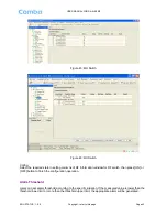
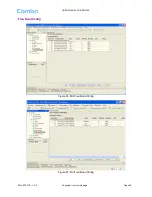
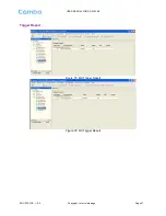
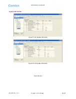
Trigger Report 


Figure 75: MU Trigger Report 


Figure 76: RU Trigger Report 

Содержание RA-5J00

Страница 1: ...T TR RI I B BA AN ND D D DI IS ST TR RI IB BU UT TE ED D A AN NT TE EN NN NA A S SY YS ST TE EM M USER MANUAL RA 5J00 III3 BR QE 1 0 0 Comba Telecom Ltd RA 5J00...

Страница 2: ...npublished work the copyright in which vests in Comba International Comba All rights reserved The information contained herein is confidential and the property of Comba and is supplied without liabili...

Страница 3: ...2 2 SYSTEM INSTALLATION CHECKLIST 19 3 3 INSTALLATION PROCEDURES 20 3 3 1 GOODS INWARDS INSPECTION 20 3 3 2 TOOLS 20 3 3 3 PREPARATION 20 3 3 4 MU CARBINET MOUNTING 20 3 3 5 MU INSTALLATION 21 3 3 6...

Страница 4: ...opyright refer to title page Page 4 5 3 ALARM INFORMATION 49 5 4 PROPERTIES INFORMATION 51 6 TROUBLESHOOTING 59 7 APPENDICES 60 7 1 APPENDIX A TOOLS FOR INSTALLATION AND MAINTENANCE 60 7 2 APPENDIX B...

Страница 5: ...24 Install Mounting Rack on the Pole 28 Figure 25 Hose Clamp Diagram 28 Figure 26 Zone Circle Diagram 29 Figure 27 Make the Zone Circle GoThrough the First Squre Hole of the Mounting Rack and Fix it o...

Страница 6: ...MU Equipment Info 53 Figure 68 RU Equipment Info 53 Figure 69 MU Site Location 54 Figure 70 RU Site Location 54 Figure 71 MU System Clock 55 Figure 72 RU System Clock 55 Figure 73 MU Comm Config 56 F...

Страница 7: ...RA 5J00 III3 ENU STATUS 1 0 0 Copyright refer to title page Page 7 0 3HISTORY Change No ENU Details Of Change 1 1 0 0 This user manual first created in Oct 2012 which referred to its Chinese manual R...

Страница 8: ...lectrical Hz Hertz ID Identification LNA Low Noise Amplifier MCU Main Control Unit MHz Megahertz MT Mobile Terminal MTBF Mean Time Between Failures NC Normally Closed NF Noise Figure NO Normally Open...

Страница 9: ...t label may accompany the symbol label Hazard labeling is supplemented by safety notices in the appropriate equipment manual These notices contain additional information on the nature of the hazard an...

Страница 10: ...ansmission loss Main feature High power bandwidth linear PA ensures signals no distortion amplification Optical fiber transmission with long distance transition at the most path loss of 10dB Has AGC f...

Страница 11: ...tle page Page 11 The figures below show the equipment enclosure layout of RA 5J00 PWR RUN ALM MODEM BTS_ALM LAN OP_A OP_A OP_A OP_A OP_A OP_A Comba OP_A OP_A 2100MHz 2600MHz 800MHz Figure 1 MU Enclosu...

Страница 12: ...J00 ENU STATUS 1 0 0 Copyright refer to title page Page 12 1270 OPE N CLOS E OPE N CLOS E OPE N CLOS E OPE N CLOS E 220 226 5 AC 10 0V 2 40V 5 0Hz 60 Hz Figure 4 Front Side and Bottom Views of RU Encl...

Страница 13: ...amplification in the MU Then the optical signals are transmitted to the RU via optical fiber The Optical TX RX Module of RU converts the DL optical signals into RF signals After amplification the sign...

Страница 14: ...T OP_A OP_A OP_A RU OP RU OP RU OP ANT ANT ANT RU OP RU OP RU OP OP IN OUT OP IN OUT OP IN OUT ANT ANT ANT ANT ANT ANT OP IN OUT OP IN OUT OP IN OUT 800MHz TX RX Figure 6 Application of one MU with 8...

Страница 15: ...internal layout for RU is shown below FSK Module EMC Module PSU 3 PSU 1 FAN FAN MCU FSK_OUT FSK_IN 1900MHz DL AWS DL 700MHz DL 1900MHz UL AWS UL 700UpperC UL 700LowABC UL Optical TX RX Module Li ion...

Страница 16: ...and RF signal convertion establish fiber optic signal link PA Module Amplifies the DL signal Duplexer Filters out the DL UL signal MCU Control and monitor the operation parameter of RU Li ion Battery...

Страница 17: ...olving installation operation or maintenance must be as far as reasonably free from danger Where there is a risk of damage to electrical systems involving adverse weather extreme temperatures wet corr...

Страница 18: ...terference from electromagnetic sources such as large electrical equipment Environmental Humidity has an adverse effect on the reliability of the equipment It is recommended to install the equipment i...

Страница 19: ...ch of the power cord and the power source has sufficient capacity Where appropriate ensure unused RF connectors are terminated Where appropriate ensure unused optical fiber connectors are protected Do...

Страница 20: ...acking list For any shortage contact Comba Telecom Systems Do not remove items from packing materials until installation 3 3 2 TOOLS See Appendix B for a full list of tools required for installation a...

Страница 21: ...le page Page 21 3 3 5 MU Installation MU is an indoor type device the installation procedures are shown as below Step 1 install right angle iron and left angle iron or laminate in the mounting rack Fi...

Страница 22: ...USER MANUAL FOR RA 5J00 ENU STATUS 1 0 0 Copyright refer to title page Page 22 Step2 Level MU in angle iron or laminate Figure 12 MU Installation Step 3 Fix the enclosure Figure 13 Fix the Enclosure...

Страница 23: ...0 Copyright refer to title page Page 23 Step 4 Finish installation Figure 14 Finish Installaiton 3 3 6 WALL MOUNTING OF RU Wall mounting steps are shown as below Step 1 mounting rack is shown in the f...

Страница 24: ...age Page 24 Step 2 use mounting rack to identify the location of four mounting holes on the wall Drill holes and fix the mounting rack on the wall using masonry bolts Figure 16 Fix the Mounting Rack o...

Страница 25: ...right refer to title page Page 25 Figure 18 Bottom of the Mounting Rack Step 3 hook the enclosure onto the mounting rack and tighten the nuts on top and bottom of the enclosure Figure 19 Hook the Encl...

Страница 26: ...efer to title page Page 26 Figure 20 Tighten the Nuts on the Top of Mounting Rack Figure 21 Tighten the Nuts on the Bottom of Mounting Rack Step 4 finish installation Three M8 Nuts with spring and pla...

Страница 27: ...NU STATUS 1 0 0 Copyright refer to title page Page 27 Figure 22 Finish Installation 3 3 7 POLE MOUNTING OF RU Pole mounting steps are shown as below Step 1 mounting rack is shown in the figure below F...

Страница 28: ...ole with hose clamp as the figure shows Figure 24 Install Mounting Rack on the Pole Hose clamp installation procedures First of all Take out the hose clamp and contrarotate the screw with a spanner to...

Страница 29: ...3 ENU STATUS 1 0 0 Copyright refer to title page Page 29 Figure 26 Zone Circle Diagram Secondly tightened the zone circle Figure 27 Make the Zone Circle GoThrough the First Squre Hole of the Mounting...

Страница 30: ...g Rack to a Suitable High Insert the Zone Circle to the Shell and Clockwise Rotate the Screw toTighten the Circle Figure 29 Rotoate the Screw till Mounting Rack Fixed On the Pole Thirdly use the same...

Страница 31: ...Copyright refer to title page Page 31 Figure 30 Enclosure Installed in Mounting Rack Step4 fix the three M8 nuts on the top of the enclosure with a spanner Figure 31 Fix the Nuts on the Top of Enclosu...

Страница 32: ...32 Fix the Nuts on the Bottom of Enclosure Step6 finish installation 3 3 8 DRIP LOOP Comba recommends that every horizontal cable entry to the equipment forms a U before it s entry to the equipment A...

Страница 33: ...is designed for all cables entries from the bottom of the enclosure The figures below present the connectors of RA 5J00 PWR RUN ALM MODEM BTS ALM LAN Figure 33 MU Front Panel Connectors AC 100V 240V...

Страница 34: ...em antenn port LAN RJ45 Ethernet connector OMT commissioning port BTS_ALM DB9 female connector reports alarm to BTS Table 6 RU Connections Identifier Functional Description AC100V 240V AC110 220V Powe...

Страница 35: ...onally acceptable colour code of the ground connection wire is green yellow Such a ground connection implements the Protective Ground Connection and must be connected to the equipment at the designate...

Страница 36: ...igure PWR RUN ALM MODEM BTS_ALM LAN OP_A OP_A OP_A OP_A OP_A OP_A Comba OP_A OP_A Fibre Optic Distribution Box 2600MHz 800MHz Figure 38 Fibre Optic Port Connection Diagram Note The length of optical f...

Страница 37: ...CTION The equipment alarms can be signaled to the BTS via voltage free relay contacts The voltage free relay connections are connected to the DB 9 port BTS_ALAM located on the MU The following figure...

Страница 38: ...RJ45 to the serial port of PC with ethernet cable supplied to achieve local monitoring and management A build in wireless modem is available for OMC connection to realize remote commissioning Connect...

Страница 39: ...d verify that the ground resistance is less than 5 Connect the equipment to the PC installed with OMT software With the MU switched on RU installed and all cablings connected apply power to the RU by...

Страница 40: ...ation please refer to OMT user manual and other references 5 1 LOCAL CONNECTIONS TO OMT After installing OMT software on the PC connection to the equipment can be done locally Double click the OMT exp...

Страница 41: ...0 0 Copyright refer to title page Page 41 5 1 2 LOCAL CONNECTION TO OMT After database configuration is done successfully the following window will pop up and select Local connection via Ethernet for...

Страница 42: ...5 255 0 Repeater IP Address 192 168 8 101 Input the IP address and the Port No and click Connect it will enter into the main window of OMT 5 2 RF INFORMATION It is recommended to configure the followi...

Страница 43: ...tate in setting columns of RF information window for RF switch then press ON or OFF button to finish the configuration operation Alarm Threshold Users can set alarm threshold according to the specific...

Страница 44: ...USER MANUAL FOR RA 5J00 ENU STATUS 1 0 0 Copyright refer to title page Page 44 Figure 47 MU Alarm Threshold Figure 48 RU Alarm Threshold Power Figure 49 MU Power...

Страница 45: ...USER MANUAL FOR RA 5J00 III3 ENU STATUS 1 0 0 Copyright refer to title page Page 45 Figure 50 RU Power Gain Figure 51 MU Gain...

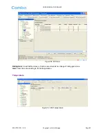
Страница 46: ...1 0 0 Copyright refer to title page Page 46 Figure 52 RU Gain Rating Gain be set before delivery Comba recommends no change of rating gain value Gain User can set according to the real application Te...

Страница 47: ...USER MANUAL FOR RA 5J00 III3 ENU STATUS 1 0 0 Copyright refer to title page Page 47 Figure 54 RU Temperature Alarm Config Figure 55 RU Alarm Config...

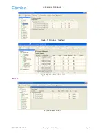
Страница 48: ...USER MANUAL FOR RA 5J00 ENU STATUS 1 0 0 Copyright refer to title page Page 48 Freq Band Config Figure 56 MU Freq Band Config Figure 57 RU Freq Band Config...

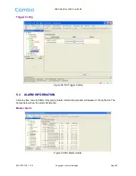
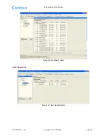
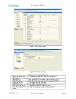
Страница 49: ...title page Page 49 Trigger Config Figure 58 RU Trigger Config 5 3 ALARM INFORMATION Click any tree node in Alarm Info group Alarm Information window will appear in the right side The figures below sh...

Страница 50: ...USER MANUAL FOR RA 5J00 ENU STATUS 1 0 0 Copyright refer to title page Page 50 Figure 60 RU Master Alarm External Alarm Figure 61 RU External Alarm...

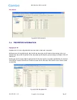
Страница 51: ...D includes Site ID Site Sub ID and slave site sub ID Set site ID according to the real situation the site sub ID should be 00 the slave site sub ID should be set according to numbers of RU FF means nu...

Страница 52: ...USER MANUAL FOR RA 5J00 ENU STATUS 1 0 0 Copyright refer to title page Page 52 Figure 64 RU Equipment ID Firmware Info Figure 65 MU Firmware Info Figure 66 RU Firmware Info...

Страница 53: ...USER MANUAL FOR RA 5J00 III3 ENU STATUS 1 0 0 Copyright refer to title page Page 53 Equipment Info Figure 67 MU Equipment Info Figure 68 RU Equipment Info...

Страница 54: ...NUAL FOR RA 5J00 ENU STATUS 1 0 0 Copyright refer to title page Page 54 Site Location Figure 69 MU Site Location Figure 70 RU Site Location Site Location input the current longitude and latitude in th...

Страница 55: ...ge Page 55 System Clock Figure 71 MU System Clock Figure 72 RU System Clock System Clock it shows the current time date information It is settable Comm Config The Comm Config information requires to b...

Страница 56: ...MS centre number of SIM card in equipment OMC Server IP OMC IP Address For equipment which support TCP IP OMC IP Port No OMC IP Port No For equipment which support TCP IP GPRS User Name Login GPRS net...

Страница 57: ...USER MANUAL FOR RA 5J00 III3 ENU STATUS 1 0 0 Copyright refer to title page Page 57 Trigger Report Figure 75 MU Trigger Report Figure 76 RU Trigger Report...

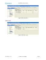
Страница 58: ...USER MANUAL FOR RA 5J00 ENU STATUS 1 0 0 Copyright refer to title page Page 58 Update Information Figure 77 MU Update Information Figure 78 RU Update Information End of Section...

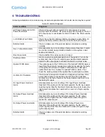
Страница 59: ...he TX RX port of the Optical TX RX Module is lower than the minimum requirement which is resulted by the faulty of the optical TX RX part of Optical TX RX Module or damaged optical fiber link If so re...

Страница 60: ...page Page 60 7 APPENDICES 7 1 APPENDIX A TOOLS FOR INSTALLATION AND MAINTENANCE The following are the recommended list of tools new installation and routine maintenance Electronic drill Allen Key Adj...

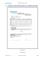
Страница 61: ...USER MANUAL FOR RA 5J00 III3 ENU STATUS 1 0 0 Copyright refer to title page Page 61 7 2 APPENDIX B RMA RETURN MATERIAL AUTHORIZATION FORM End of Section End of Document...

Страница 62: ...USER MANUAL FOR RA 5J00 ENU STATUS 1 0 0 Copyright refer to title page Page 62...

Отзывы: