


E.DO GRIPPER INSTALLATION
25
Comau Robotics Product Instruction
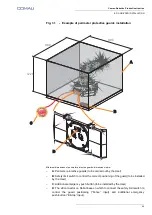
Fig. 3.1
- Example of perimeter protective guards installation
Minimum dimensions of perimeter protective guards; dimensions in mm
–
A
: Perimeter protective guards (to be carried out by the User)
–
B
: Safety limit switch to control the correct positioning of the guard (to be installed
by the User)
–
C
: Additional emergency push-button (to be installed by the User)
–
D
: The J8 connector on Robot base on which to connect the safety limit switch to
control the guard positioning (“Fence” input) and additional emergency
push-button (“E-Stop” input).
A
B
D
C
1220
900
900
Содержание e.DO
Страница 27: ......
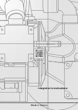
Страница 28: ...Made in Comau Integration to instructions...