background image

S

ection

 5— o

peration

16

Starting the Engine

WARNING! 

This tractor is equipped with a safety 

interlock system designed for the protection of the 

operator. Do not operate the tractor if any part of the 

system is malfunctioning. Periodically check the 

function of the interlock system for proper operation.


WARNING! 

For personal safety, the operator must 

be sitting in the tractor seat when starting the 

engine.

NOTE: 

Refer to the Engine Operator’s Manual for oil fill-up 

instructions and refer to the Assembly & Set-Up section for 

gasoline fill-up instructions.
1. 

Operator must be sitting in the tractor seat.

2. 

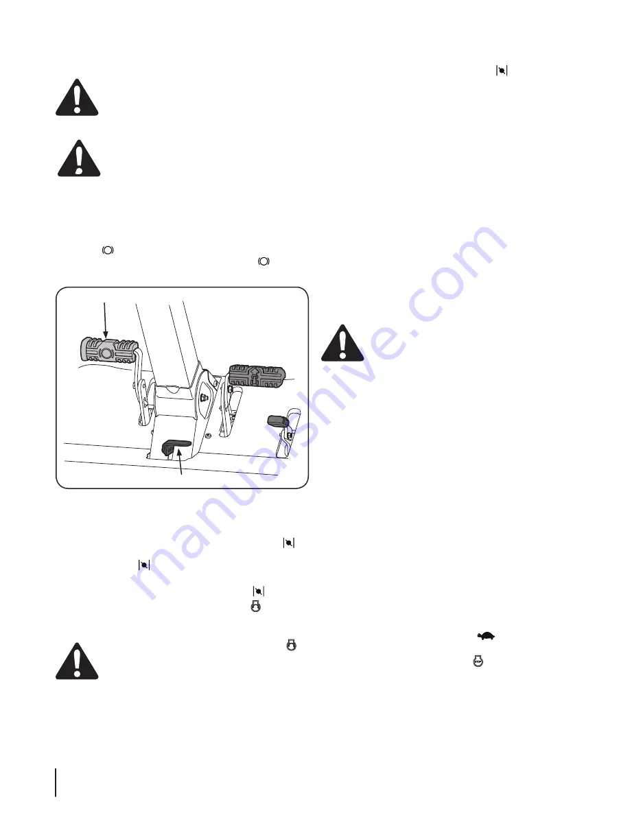
Engage the parking brake by pressing forward on the brake 

pedal 

, then press down on the parking break/cruise 

control lever and then release the brake pedal 

. Refer to 

Figure 5-1.

Brake Pedal

Parking Brake/Cruise Control Lever

Figure 5-1

3. 

Make certain the PTO switch is in the disengaged (down) 

position. Refer to Figure 5-1.

4. 

Pull the choke knob (if equipped) up into the CHOKE   

position or move the throttle/choke control (if equipped) 

into the CHOKE   position.

NOTE: 

If the engine is warmed up, it may not be necessary to 

place the throttle/choke control in the CHOKE   position.

5. 

Turn the ignition key clockwise to the START   position. 

After the engine starts, release the key. It will return to the 

run position.

CAUTION: 

Do NOT hold the key in the START 

position for longer than ten seconds at a time. Doing 

so may cause damage to your engine’s electric 

starter.

6. 

As the engine warms up, gradually pull the throttle/choke 

control lever (if equipped) rearward past the choke detent 

position or push the choke knob (if equipped) down into 

the OFF position.

NOTE: 

Do NOT leave the throttle/choke control (if equipped) 

or the choke (if equipped) in the CHOKE   position while 

operating the tractor. Doing so will result in a “rich” fuel 

mixture and cause the engine to run poorly.

7. 

Allow the engine to run for a few minutes at mid throttle 

before putting the engine under load.

8. 

Observe the hour meter/indicator panel. If the battery indicator 

light or oil pressure light come on, immediately stop the engine. 

Have the tractor inspected by your Cub Cadet dealer.

Cold Weather Starting

When starting the engine at temperatures near or below freezing, 

ensure the correct viscosity motor oil is used in the engine and the 

battery is fully charged. Start the engine as follows:
1. 

Be sure the battery is in good condition. A warm battery 

has much more starting capacity than a cold battery.

2. 

Use fresh winter grade fuel. Winter grade gasoline has 

higher volatility to improve starting. Do not use gasoline 

left over from summer.

3. 

Follow the previous instruction for Starting the Engine.

Using Jumper Cables To Start Engine

WARNING! 

Batteries contain sulfuric acid and 

produce explosive gasses. Make certain the area is 

well ventilated, wear gloves and eye protection, and 

avoid sparks or flames near the battery.

If the battery charge is not sufficient to crank the engine, 

recharge the battery. If a battery charger is  unavailable and 

the tractor must be started, the aid of a booster battery will be 

necessary. Connect the booster battery as follows:
1. 

Connect the end of one cable to the disabled tractor 

battery’s positive terminal; then connect the other end of 

that cable to the booster battery’s positive terminal.

2. 

Connect one end of the other cable to the booster 

battery’s negative terminal; then connect the other end of 

that cable to the  frame of the disabled tractor, as far from 

the battery as possible.

3. 

Start the disabled tractor following the normal starting 

instructions previously provided; then disconnect the 

jumper cables in the exact reverse order of their connection.

4. 

Have the tractor’s electrical system checked and repaired 

as soon as possible to eliminate the need for jump starting.

Stopping the Engine

1. 

Place the PTO switch in the disengaged position.

2. 

Engage the parking brake.

3. 

Move the throttle/choke control (if equipped) or the 

throttle (if equipped) to the SLOW 

 position and allow 

the engine to idle for about one minute.

4. 

Turn the ignition key to the STOP   position and remove 

the key from the ignition switch.

NOTE: 

Always remove the key from the ignition switch to prevent 

accidental starting or battery discharge if the equipment is left 

unattended.

Содержание RZT S Series

Страница 1: ...RULES AND INSTRUCTIONS IN THIS MANUAL BEFORE ATTEMPTING TO OPERATE THIS MACHINE FAILURE TO COMPLY WITH THESE INSTRUCTIONS MAY RESULT IN PERSONAL INJURY LES DISTRIBUTIONS RVI LIMITÉE 2955 JEAN BAPTISTE DESCHAMPS LACHINE QUEBEC H8T 1C5 MTD LLC P O BOX 361131 CLEVELAND OHIO 44136 0019 OPERATOR S MANUAL RZT S Series Tractor 769 09702 2 4 14 ...

Страница 2: ...on available at the time of printing Review this manual frequently to familiarize yourself with the machine its features and operation Please be aware that this Operator s Manual may cover a range of product specifications for various models Characteristics and features discussed and or illustrated in this manual may not be applicable to all models The manufacturer reserves the right to change pro...

Страница 3: ...jects which ricochet can cause serious injury to the eyes 9 Wear sturdy rough soled work shoes and close fitting slacks and shirts Loose fitting clothes and jewelry can be caught in movable parts Never operate this machine in bare feet or sandals 10 Be aware of the mower and attachment discharge direction and do not point it at anyone Do not operate the mower without the discharge cover or entire ...

Страница 4: ...s that operators age 60 years and above are involved in a large percentage of riding mower related injuries These operators should evaluate their ability to operate the riding mower safely enough to protect themselves and others from serious injury 29 If situations occur which are not covered in this manual use care and good judgment Contact your customer service representative for assistance Slop...

Страница 5: ... and allow extra distance to stop 13 Do not shift to neutral and coast downhill Service Safe Handling of Gasoline 1 To avoid personal injury or property damage use extreme care in handling gasoline Gasoline is extremely flammable and the vapors are explosive Serious personal injury can occur when gasoline is spilled on yourself or your clothes which can ignite Wash your skin and change clothes imm...

Страница 6: ...ment specifications may lead to improper performance and compromise safety 12 Do not change the engine governor settings or over speed the engine The governor controls the maximum safe operating speed of the engine 13 Maintain or replace safety and instruction labels as necessary 14 Observe proper disposal laws and regulations for gas oil etc to protect the environment 15 According to the Consumer...

Страница 7: ...his machine may pick up and throw and objects which can cause serious personal injury BYSTANDERS Keep bystanders helpers children and pets at least 75 feet from the machine while it is in operation WARNING SLOPE OPERATION Do not operate this machine on a slope greater than 15 degrees DANGER ROTATING BLADES To reduce the risk of injury keep hands and feet away Do not operate unless discharge cover ...

Страница 8: ...ee Figure 1 and Figure 2 4 Adjust gauge up or down until the left corner touches the slope See Figure 1 and Figure 2 5 If there is a gap below the gauge the slope is too steep for safe operation See Figure 2 above 1 5 d a s h e d l i n e Slope Gauge Figure 2 Figure 1 15 Slope 15 Slope WARNING Slopes are a major factor related to tip over and roll over accidents which can result in severe injury or...

Страница 9: ...ctions on raising and lowering the deck 3 Disengage the parking brake 4 Engage the transmission bypass rods on each side of the tractor then carefully roll the tractor off the shipping pallet The transmission bypass rods one for each the RH and LH transmission are located on the rear of the tractor just inside each rear wheel Engage the bypass rods by pulling each one out and to the right then let...

Страница 10: ...witch and seat pan attached A second person may be needed to hold the seat 1 Cut any straps securing the seat assembly to the tractor Remove any packing material NOTE Be careful not to cut the wiring harness connecting the seat and the seat switch in the bottom of the seat 2 Remove the two shoulder screws in the seat pan as shown in Figure 3 4 3 Rotate the seat into position and secure the seat in...

Страница 11: ...itive battery terminal with the bolt and hex nut See Figure 3 9 Figure 3 9 2 Remove the plastic cover if present from the negative battery terminal and attach the black cable to the negative battery terminal with the bolt and hex nut See Figure 3 9 3 Position the red rubber boot over the positive battery terminal to help protect it from corrosion NOTE If the battery is put into service after the d...

Страница 12: ...upward to raise the deck When the desired height is attained move the lift handle to the right until fully in the index notch PTO Knob The PTO Power Take Off knob is located on the RH console to the right of the operator s seat The PTO knob operates the electric PTO clutch mounted on the bottom of the engine crankshaft Pull the knob upward to engage the PTO clutch or push the knob downward to dise...

Страница 13: ...ator of maintenance intervals for changing the engine oil air filter service low engine and low battery warnings Change Oil The LCD will display the letters CHG followed by the letters OIL followed by the letters SOON then finally followed by the meter s accumulated time CHG OIL SOON TIME will alternate on the display for 7 minutes after the meter reaches 50 hours This oil service minder intervall...

Страница 14: ... feature NOTE Cruise control can NOT be engaged at the tractor s fastest ground speed If the operator should attempt to do so the tractor will automatically decelerate to the fastest optimal mowing ground speed NOTE The parking brake must be set if the operator leaves the seat with the engine running or the engine will automatically shut off FAST SLOW FAST SLOW PARK BRAKE CRUISE CTRL LOCK PEDAL I2...

Страница 15: ...several minutes to cool before refueling Tighten the fuel cap securely Before Operating Your Tractor Before you operate the tractor study this manual carefully to familiarize yourself with the operation of all the instruments and controls It has been prepared to help you operate and maintain your tractor efficiently This engine is certified to operate only on clean fresh unleaded regular gasoline ...

Страница 16: ...ht or oil pressure light come on immediately stop the engine Have the tractor inspected by your Cub Cadet dealer Cold Weather Starting When starting the engine at temperatures near or below freezing ensure the correct viscosity motor oil is used in the engine and the battery is fully charged Start the engine as follows 1 Be sure the battery is in good condition A warm battery has much more startin...

Страница 17: ...rd or reverse 6 To travel in reverse check that the area behind is clear then slowly push forward on the reverse drive pedal with the ball of your foot NOT your heel until the desired speed is achieved See Figure 5 2 CAUTION Do NOT attempt to change the direction of travel when the tractor is in motion Always bring the tractor to a complete stop before moving the tractor from forward to reverse or...

Страница 18: ...object injury keep bystanders helpers children and pets at least 75 feet from the machine while it is in operation Stop machine if anyone enters the area The following information will be helpful when using the cutting deck with your tractor WARNING Plan your mowing pattern to avoid discharge of materials toward roads sidewalks bystanders and the like Also avoid discharging material against a wall...

Страница 19: ... jelly or grease to both terminals CAUTION If removing the battery for cleaning disconnect the NEGATIVE Black wire from its terminal first followed by the POSITIVE Red wire When re installing the battery always connect the POSITIVE Red wire its terminal first followed by the NEGATIVE Black wire Be certain that the wires are connected to the correct terminals reversing them could result in serious ...

Страница 20: ...rviceability Removing The Tractor From Storage 1 Check the engine oil 2 Fully charge the battery and inflate the tires to the recommended pressure 3 If drained before storing fill the fuel tank with clean fresh gasoline 4 Add clean fresh fuel 5 Start the engine and allow to idle for a few minutes to ensure engine is operating properly 6 Drive the tractor without a load to make certain all the trac...

Страница 21: ... under inflated Have it inspected and serviced by a qualified tire mechanic 10 Turn the water off and detach the hose coupler from the water port on your deck s surface 11 After cleaning your deck return to the operator s position and engage the PTO Keep the cutting deck running for a minimum of two minutes allowing the underside of the cutting deck to thoroughly dry Lubrication WARNING Before lub...

Страница 22: ...le and is used to help adjust the other hanger links 4 Using a wrench raise or lower the left side of the deck by turning the adjustment gear See Figure 6 5 The deck is properly leveled when both blade tip measurements are equal Retighten the hex bolt on the front left deck hanger bracket when proper adjustment is achieved Leveling the Deck Front To Rear NOTE Check the tractor s tire pressure befo...

Страница 23: ...ft handle in the desired mowing height setting d Reinsert the shoulder bolts with each gauge wheel into the index hole that leaves approximately inch between the bottom of the wheel and the pavement Adjusting the Rollers 50 54 Decks To adjust the rollers proceed as follows 1 To change the height of the rollers remove the bow tie cotter pin and slide the J hook out until the end is out of current h...

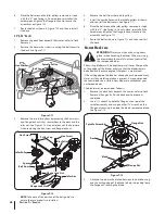
Страница 24: ...stall the battery by repeating the above steps in the reverse order WARNING Always connect the positive lead to the battery before connecting the negative lead This will prevent sparking or possible injury from an electrical short caused by contacting the tractor body with tools being used to connect the cables Charging the Battery Test and if necessary recharge the battery after the tractor has b...

Страница 25: ...RNING Use caution to avoid pinching your fingers when rolling the belt off the PTO pulley 4 Pull the left side of the belt rearward and downward while manually turning the PTO pulley to the right until the belt rides out onto the edge of the lower sheave of the pulley NOTE If pulling the right side of the belt turn the pulley left 5 While still holding the belt downward continue turning the PTO pu...

Страница 26: ... into the highest mowing position and slide the deck out from beneath the tractor Deck Installation Install the deck on the tractor as follows 1 Place the deck lift handle in the highest mowing position See Figure 7 3 2 Slide the deck under the tractor on the right side of the tractor lining up the deck hanger brackets and the deck lift arms 3 Once the deck is under the tractor move the deck lift ...

Страница 27: ...bly See Figure 7 8 7 Route the belt as shown in Figure 7 7 and then reinstall the deck 46 Deck 1 Remove the deck from beneath the tractor refer to Deck Removal 2 Remove the hex washer screws securing the belt covers to the deck See Figure 7 9 PTO Pulley Idler Pulley Idler Pulley Belt Cover Hex Washer Screws Belt Guard Spindle Pulley Spindle Pulley Idler Arm Figure 7 9 3 Remove the two idler pulley...

Страница 28: ...ce the belt around the idler pulleys removed in step 3 with the V side facing in Once in place reinstall all the hardware and tighten the flange lock nut to secure the assembly See Figure 7 12 7 Route the belt as shown in Figure 7 12 and then reinstall the deck Mower Blade Care WARNING Protect your hands by using heavy gloves when handling the blades When servicing the mower deck be careful not to...

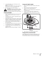
Страница 29: ... or a hand file to sharpen the blades 3 Replace any blade with severe nicks or dents that cannot be removed by filing 4 Check the balance of the blade after sharpening by placing it on a blade balancer Do not use unbalanced blades 5 If the blade dips on one end file stock off of the cutting surface on that end NOTE Blades that cannot be easily balanced REPLACE Changing the Spindle Assembly 1 Remov...

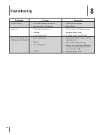
Страница 30: ...deck adjustment 2 Sharpen or replace blade 3 Check tire pressure in all four tires Mower will not mulch grass If Equipped w Mulching Kit 1 Engine speed too low 2 Wet grass 3 Excessively high grass 4 Dull blade 1 Place throttle choke control lever in FAST rabbit position 2 Do not mulch when grass is wet 3 Mow once at a high cutting height then mow again at desired height or make a narrower cutting ...

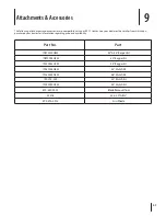
Страница 31: ...hich you purchased your tractor for information regarding price and availability Part No Part 19B70020OEM 42 46 Bagger Kit 19B70004OEM 50 Bagger Kit 19A70043OEM 54 Bagger Kit 19A30006OEM 42 Mulch Kit 19A30005OEM 46 Mulch Kit 190 193 000 50 Mulch Kit 19A70042OEM 54 Mulch Kit 490 850 0005 Blade Removal Tool 22216 32 oz STA BIL 490 290 0013 Sun Shade ...

Страница 32: ... Blade RZT S46 942 04053C 2 in 1 Blade RZT S50 742 05056 2 in 1 Blade RZT S54 918 04822A Spindle Assembly RZT S42 918 05078 Spindle Assembly RZT S46 918 04125B Spindle Assembly RZT S50 618 06978 Spindle Assembly RZT S54 734 04155 Deck Wheel 925 1707D Battery 951 12179B Gas Cap 946 04830B Throttle Choke Control Cable Kohler engines 746 05131 Throttle Control Cable Kawasaki engines 746 1085A Choke C...

Страница 33: ...ts Component Part Number and Description 631 04288 Chute Deflector RZT S42 RZT S46 631 05162 Chute Deflector RZT S50 RZT S54 634 04293 Wheel Assembly RZT S42 634 04128 Wheel Assembly RZT S46 RZT S50 634 04711 Caster Wheel Assembly ...

Страница 34: ...RAL EMISSIONS WARRANTY COVERAGE MTD Consumer Group Inc warrants to the ultimate purchaser and each subsequent purchaser that the outdoor equipment is 1 designed built and equipped so as to conform with all applicable regulations and 2 free from defects in materials and workmanship that cause the failure of a warranted part for a period of two years The warranty period begins on the date the outdoo...

Страница 35: ...nc demonstrates that the outdoor equipment has been abused neglected or improperly maintained and that such abuse neglect or improper maintenance was the direct cause of the need for repair or replacement of the part That notwithstanding any adjustment of a component that has a factory installed and properly operating adjustment limiting device is still eligible for warranty coverage Further the c...

Страница 36: ...stments clutch adjustments deck adjustments and normal deterioration of the exterior finish due to use or exposure d Service completed by someone other than an authorized service dealer e MTD does not extend any warranty for products sold or exported outside of Canada including possessions and territories f Replacement parts that are not genuine MTD parts g Transportation charges and service calls...

Страница 37: ...E RESPECTIVE MANUFACTURERS SERVICE DEALERS Belts light bulbs clutch parts friction wheels grass bags tires seats rider deck wheels and cutting blades are covered by a 60 day limited warranty Batteries are warranted against defect for 90 days at 100 of their value and 50 of their value for the period between the 91st day and the 120th day Fuses shear bolts and blade adapters are considered consumab...

Страница 38: ...Notes 38 ...

Отзывы: