background image

8

4

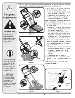
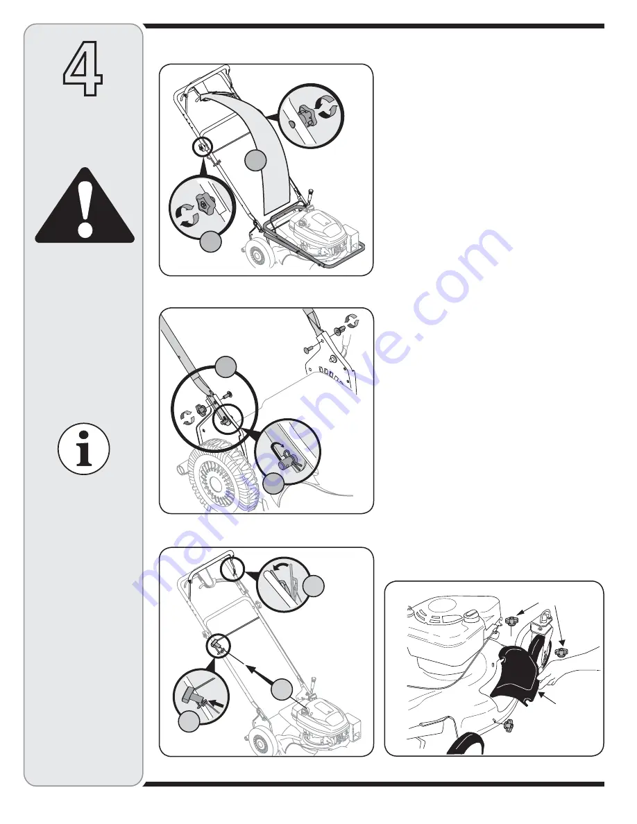
1.  Remove loose parts and any packing material which 

may be between upper and lower handles. 
a. 

Pull up and back on the upper handle to raise the 
handle from position A. See Figure 1.

b.  Tighten hand knobs 

(star knobs) 

securing upper 

handle to lower handle. Make sure that each 
carriage bolt is seated properly in the handle.

NOTE: 

On some models wing nuts have been replaced 

with star knobs. Figures show wing nuts only.

2.  Locate hairpin clip in one hole on the weld pin on each 

side of lower handle.
a.  Remove hairpin clip from this hole. Using a pair of 

pliers, insert hairpin clip into the other hole on the 
weld pin. Repeat on other side. 

b.  Place one carriage bolt (found in the hardware 

pack included with your unit) in the upper hole of 
the right handle mounting bracket from the inside 
outward. See Figure 2. Secure with one wing nut


(star knobs)

. Repeat process on the left side.

3.  The rope guide (pigs tail) is part of the grass catcher 

support rod attached to the lower handle. See Figure 3.
a.  Hold the blade control handle against the upper 

handle.  Position A.

b.  Pull the starter rope out of the engine slowly until it 

extends past the rope guide (pigs tail). Position B.

c.  Guide the starter rope around the rope guide 

(pig tail) until the rope is securely in the center.  
Position C.

d.  Tighten rope guide wing nut (star knob).

4.  Insert post on cable ties into holes provided on the 

lower handle. Pull cable tie tight and trim excess. See 
Figure 4.

NOTE: Your unit is shipped as a mulcher with the 
mulching plug installed.

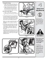
Figure 3

Figure 2

Figure 1

Figure 4

Disconnect and 
ground the spark 
plug wire as instruct-
ed in the separate 
engine manual.

IMPORTANT

This unit is shipped 
WITHOUT GASOLINE 
or OIL.  After assembly, 
service engine with 
gasoline and oil as 
instructed in the separate 
engine manual packed 
with your unit. 

Setup and 

Adjustments

Your mower is shipped 
with the handle in the 
higher height position.
NOTE: Each end of 
the lower handle must 
be placed in the same 
relative position.

WARNING

NOTE: 

This owner’s manual covers various models of lawnmowers. The units illustrated may vary slightly 

from your unit. Follow only those instructions which pertain to your model lawnmower.

Wing Nuts

Mulching
Plug

A

B

A

B

A

C

B

Содержание 978

Страница 1: ...y OPERATOR S MANUAL IMPORTANT READ SAFETY RULES AND INSTRUCTIONS CAREFULLY BEFORE OPERATING EQUIPMENT PRINTED IN U S A LES DISTRIBUTIONS RVI LIMITÉE 2955 JEAN BAPTISTE DESCHAMPS LACHINE QUEBEC H8T 1C5 21 Self Propelled Rotary Mower Model Series 900 12 22 10 769 04157C Model 978 shown ...

Страница 2: ...onsible for all engine related issues in terms of performance power rating specifications warranty and service Depending on the engine manufacturer more information is included in this publication or packed separately with this product Slope Gauge 3 Safe Operation Practices 4 Safety Symbols 7 Set Up Adjustments 8 Operation 10 Maintenance Off Season Storage 12 Trouble Shooting 16 Replacement Parts ...

Страница 3: ... and you could slip resulting in serious injury Operate RIDING mowers up and down slopes never across the face of slopes Operate WALK BEHIND mowers across the face of slopes never up and down slopes Sight and hold this level with a vertical tree or a corner of a building or a fence post F o l d a l o n g d o t t e d l i n e r e p r e s e n t s a 1 5 s l o p e 15 Use this page as a guide to determi...

Страница 4: ... a fall caused by slipping or tripping Do not hold on to the mower if you are falling release the handle immediately 14 Never pull the mower back toward you while you are walking If you must back the mower away from a wall or obstruction first look down and behind to avoid tripping and then follow these steps a Step back from the mower to fully extend your arms b Be sure you are well balanced with...

Страница 5: ... them 1 Keep children out of the mowing area and under the watchful care of a responsible adult other than the operator 2 Be alert and turn mower off if a child enters the area 3 Before and while moving backwards look behind and down for small children 4 Use extreme care when approaching blind corners doorways shrubs trees or other objects that may obscure your vision of a child who may run into t...

Страница 6: ...g 9 Grass catcher components discharge cover and trail shield are subject to wear and damage which could expose moving parts or allow objects to be thrown For safety protection frequently check components and replace immediately with original equipment manufac turer s O E M parts only listed in this manual Use of parts which do not meet the original equipment specifications may lead to improper pe...

Страница 7: ...hands and feet away from rotating parts DANGER THROWN DEBRIS Remove objects that can be thrown by the blade in any direction Wear safety glasses DANGER SLOPES Use extra caution on slopes Do not mow slopes greater than 15 WARNING GASOLINE IS FLAMMABLE Allow the engine to cool at least two minutes before refueling WARNING CARBON MONOXIDE Never run an engine indoors or in a poorly ventilated area Eng...

Страница 8: ...e control handle against the upper handle Position A b Pull the starter rope out of the engine slowly until it extends past the rope guide pigs tail Position B c Guide the starter rope around the rope guide pig tail until the rope is securely in the center Position C d Tighten rope guide wing nut star knob 4 Insert post on cable ties into holes provided on the lower handle Pull cable tie tight and...

Страница 9: ...scharge chute with wing nuts See Figure 5 7 The height adjuster determines the cutting height of the mower The adjuster is located above the left rear wheel To adjust the cutting height pull the lever out and away from the mower and then move it forward or back to select a new cutting height See Figure 9 NOTE Some models are equipped with optional front wheel casters Refer to the Operation Section...

Страница 10: ...ront wheel cutting height is determined by the selection of one of six positions in each caster assembly See Figure 9 To adjust remove the wing nut from the axle bolt Slide the axle bolt and spring washer from the assembly and select a cutting height With the spring washer on the axle bolt reinsert in the square hole desired through the wheel assembly and secure with the wing nut previously remove...

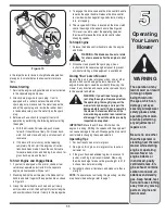
Страница 11: ...n and pull slowly until resistance is felt then pull rapidly to start engine and avoid kickback Return it slowly to the rope guide 4 To engage the drive squeeze the drive control handle towards the upper handle Release the drive control to slow down when negotiating an obstacle making a turn or stopping 5 The six speed shift lever is located on the drive clutch control housing on the upper handle ...

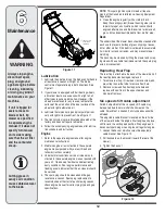
Страница 12: ...is essential to engine performance and life Be certain to remove all grass dirt and combustible debris from muffler area Deck The underside of the mower deck should be cleaned after each use to prevent a buildup of grass clippings leaves dirt or other matter If this debris is allowed to accumulate it will invite rust and corrosion and may prevent proper mulching The deck may be cleaned by tilting ...

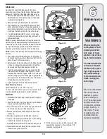
Страница 13: ... marked bottom or with part number facing away from the adapter Align the blade bell support over the blade with the tabs in the holes of the blade and insert the hex bolt 8 Tighten the hex bolt to the torque listed below Blade Mounting Torque Center Bolt 450 in lb min 600 in lb max To insure safe operation of your unit ALL nuts and bolts must be checked periodically for correct tightness Belt Car...

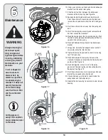
Страница 14: ... Lift off the lower pulley assembly and remove the old belt from around the crankshaft 15 Place the new belt over the transmission pulley Start the belt in pulley groove and rotate pulley until belt is seated in transmission pulley 16 Place belt between idler pulley and the belt keeper bracket 17 Using pliers rotate the belt keeper bracket so that it snaps into slot on the idler bracket 18 Tighten...

Страница 15: ...l for correct engine storage instructions 4 Coat mower s cutting blade with chassis grease to prevent rusting 5 Store mower in a dry clean area Do not store next to corrosive materials such as fertilizer NOTE When storing any type of power equipment in a poorly ventilated or metal storage shed care should be taken to rust proof the equipment Using a light oil or silicone coat the equipment especia...

Страница 16: ... Engine overheats 1 Fill crankcase with proper oil 2 Refer to the engine manual packed with your unit 3 Remove blower housing and clean 4 Refer to engine manual 1 Engine oil level low 2 Dirty air filter 3 Air flow restricted 4 Carburetor not adjusted properly Occasional skip hesitates at high speed 1 Adjust gap to 030 Refer to engine manual 2 Refer to engine manual 1 Spark plug gap too close 2 Car...

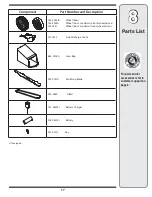
Страница 17: ...er and Description 734 2044B Wheel Rear 734 2004A Wheel Front models w o front wheel casters 734 1857 Wheel Front models w front wheel casters 731 1832 Side Discharge Chute 664 0076A Grass Bag 942 0741A Mulching Blade 954 0460 V Belt 725 04329 Battery Charger 925 04323 Battery 925 0201 Key If Equipped ...

Страница 18: ...as lubricants filters blade sharpening tune ups brake adjustments clutch adjustments deck adjustments and normal deterioration of the exterior finish due to use or exposure d Service completed by someone other than an authorized service dealer e MTD does not extend any warranty for products sold or exported outside of Canada including possessions and territories f Replacement parts that are not ge...

Страница 19: ...HROUGH THE RESPECTIVE MANUFACTURERS SERVICE DEALERS Belts light bulbs clutch parts friction wheels grass bags tires seats rider deck wheels and cutting blades are covered by a 60 day limited warranty Batteries are warranted against defect for 90 days at 100 of their value and 50 of their value for the period between the 91st day and the 120th day Fuses shear bolts and blade adapters are considered...

Страница 20: ...20 NOTES ...
Отзывы: