background image

55

www.colormetric.net

Color

metrics P3300

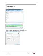
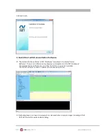
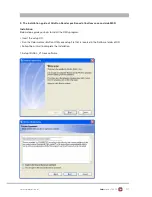
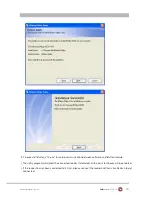
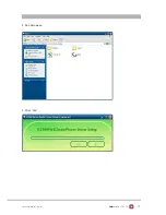
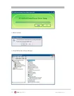
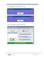
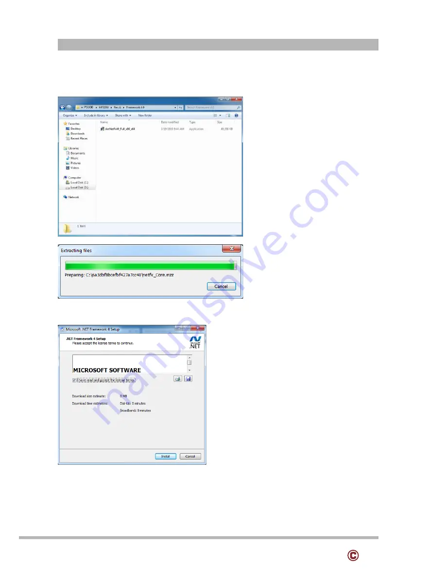
2.1 Double-click to install. 

2. Install framework 4.0

2.2 Select “I have read and accept the license terms. And click Install..

Содержание P3300

Страница 1: ...Errors excepted subject to change www colormetric net P3300 User Manual Version 1 0 ...

Страница 2: ...written permission of the publisher All products and trade names described within are mentioned for identification purpose only No affiliation with or endorsement of the manufacturer is made or implied Product names and brands appearing in this manual are registered trademarks of their respective companies The information published herein has been checked for accuracy as of publishing time No repr...

Страница 3: ... this could cause fire or electrical shock 9 If one of the following situations arises get the equipment checked by a service personnel a The power cord or plug is damaged b Liquid has penetrated into the equipment c The equipment has been exposed to moisture d The equipment does not work well or you can not get it work according to user manual e The equipment has dropped and damaged 10 Do not lea...

Страница 4: ... Memory 14 5 3 MSR 14 5 4 VFD 15 5 5 2nd HDD Kit 15 5 6 8 2nd Monitor 16 5 7 Adapter 17 5 8 1D 2D i Button with RFID module 18 6 DEVICE DRIVER INSTALLATION 19 6 1 Resistive Type Touch Panel P Cup 19 6 2 MagStripe Card Reader Configuration Utility 25 6 3 Fingerprint Reader 42 6 4 RFID 52 6 5 Configuration Utility of I Button Reader 58 6 6 Installation and Testing of Smart Card Reader 66 7 BIOS UTIL...

Страница 5: ...ptional Accessories Modules MSR 1D 2D barcode scanner RFID 13 56 MHz iButton Smart card reader Fingerprint reader MODULES MSR 1D 2D BARCODE NER RFID 13 56MHZ IBUTTON SMARTCARD REA FINGERPRINT REA Accessories Build in VFD Pole VFD 8 pole customer display 15 pole customer display UPS battery Note Nearly all modules are also available as 2 in 1 or 3 in 1 solution ...

Страница 6: ...ic in 10 PS2 K B 11 USB 2 0 X 2 12 RJ45 COM3 13 RJ11 Cash Drawer 14 Parallel port Option 15 Power Button 16 MSR Smart Card i Button Fingerprint RFID Option 17 HDD Cover 18 Antenna Cover 19 8 2nd Display VFD Cover 20 Memory Cover 21 Power LED 22 Cover for Internal access of 2nd HDD Adapter Please make sure 19V DC plug in the right direction before plugging in DC jack ...

Страница 7: ...on Brightness Touch Panel Tilt Angle Intel Celeron G540 processor 2M Cache 2 50GHz H61 One SO DIMM socket supports DDR3 1066 1333MHZ up to 8GB Line out Mic in RJ45 10 100 1000 Base T 5 USB 2 0 2 5 SATA HDD SSD AMI BIOS DC 19V 150W Adaptor Heat sink Fan X1 410 W x 385 2 H x 296 4 D mm 0 C 35 C 20 C 60 C 20 80 non condensing 17 inch TFT Active Matrix Display 1028 1024 Pixels 250 cd m2 350cd m2 Optio...

Страница 8: ...7 PD5 Parallel Port DATA5 8 PD6 Parallel Port DATA6 9 PD7 Parallel Port DATA7 10 ACK Printer Acknowledge 11 BUSY Printer Busy 12 PE Printer Paper End 13 SLCT Printer Select Pin NO Pin Name Description 14 AFD Printer Auto Line Feed 15 ERR Printer Error 16 INIT Printer Initialize 17 SLIN Printer Select Input 18 GND Ground 19 GND Ground 20 GND Ground 1 COM 5 for Touch Panel CN 7 Pin Function Pin Func...

Страница 9: ...V 8 USB D 9 USB D 10 GND Pin NO Pin Name Description 1 GND Ground 2 GND Ground 3 Line OUT R Line out 4 Line OUT L Line out 5 Detect Detect 3 Lin out J3 5 Mic 6 Speaker SPK1 SPK2 Pin NO Pin Name Description 1 GND Ground 2 GND Ground 3 Mic R Mic 4 Mic L Mic 5 Detect Detect Pin NO Pin Name Description 1 Speaker 2 Speaker ...

Страница 10: ...xE1 9 RxE1 10 RxE0 11 RxE0 12 RxO3 13 RxO3 14 GND 15 RxOCLK 16 RxOCLK 17 GND 18 RxO2 19 RxO2 20 RxO1 21 RxO1 22 RxO0 23 RxO0 24 GND 25 NC GND for G type 26 NC 27 NC GND for G type 28 5V 29 5V 30 5V 8 Inverter C14 Pin NO Pin Name Description 1 VCC 12V 2 GND Ground 3 NC NC 4 BKL_CTL Back Light Brightness 5 BKL_EN Back Light Enable ...

Страница 11: ...ignal Function Pin Signal 1 CD Carrier Detect IN 6 DSR 2 RD Receive Data IN 7 RTS 3 TD Transmit Data OUT 8 CTS 4 DTR Data Terminal Ready OUT 9 Ring 5V 5 GND Ground COM4 port Warning COM4 RJ45 Connector for ex network device If you are using on the network device w 1 2 3 4 56 78 Jumper for COM4 Voltage Setting Item 1 19V DC Input 2 COM2 3 COM1 4 E SATA USB 5 USB 2 0 X2 6 VGA 7 LAN port 8 Line out 9...

Страница 12: ...Green Data Transfer 4 Ground Black Cable Ground Shell Shield Drain Wire Pin Signal Name Direction 1 Frame GND 2 Drawer Kick out drive signal 1 Output 3 Cash Drawer Status Input 4 12V 5 N C 6 Signal GND Pin I O Function 9 Key Plugged Hole 10 Sync Ground 11 In Monitor ID 0 12 In Monitor ID 1 13 Out Horizontal Sync 14 Out Vertical Sync 15 In Monitor ID 3 Pin Wire Colour Description 1 White Orange D0 ...

Страница 13: ...ww colormetric net Colormetrics P3300 Pin Signal Name 1 DC IN 19V 2 Ground 3 N C 8 DC Jack Pin Description Pin Description 1 GND U1 5V 2 TX U2 D 3 TX U3 D 4 GND U4 GND 5 RX 6 RX 7 GND 9 eSATA USB connector ...

Страница 14: ...SSEMBLY DISASSEMBLY 5 1 HDD 5 2 Memory 1 Unscrew 2 screws and remove the HDD cover 2 Install HDD with 4 screws 1 2 1 2 1 Unscrew 1 screw and remove the memory cover 2 Install HDD with 4 screws 5 3 MSR 1 2 1 Remove MSR cover 2 Install MSR with two screws ...

Страница 15: ...15 www colormetric net Colormetrics P3300 1 Remove the cover 2 Plug VFD cable into the 1 6 pin connector 3 Install VFD with two screws 5 5 2nd HDD Kit 5 4 VFD 3 1 2 1 2 ...

Страница 16: ...ble as the position shown in the picture 1 2 Install HDD kit with two screws 3 Plug e SATA cable into the position shown in the picture 3 5 6 8 2nd Monitor 1 3 2 3 1 Remove the cover 2 Plug cable into the 1 4 pin connector 3 Install 8 2nd Monitor with two screws ...

Страница 17: ...s and then remove the cover 2 Assemble the adapter bracket with two screws 3 Assemble the back cover the stand with two screws The adapter bracket of P3300 is only for P3300 standard adapter Model name FSP150 150W Please don t assemble other type adapter into the stand Note ...

Страница 18: ...rmetric net Colormetrics P3300 1 Cable installation For I Button RFID 1D 2D barcode scanner please connect the cable as shown in figure 5 8 1D 2D i Button with RFID module 2 Fix the screws as shown in below figure ...

Страница 19: ...19 www colormetric net Colormetrics P3300 6 DEVICE DRIVER INSTALLATION 6 1 Resistive Type Touch Panel and P CAP 1 Click Next 2 Click Next 2 Click Next ...

Страница 20: ...20 www colormetric net Colormetrics P3300 3 Click Next 4 Select None Click Next 5 Click OK ...

Страница 21: ...21 www colormetric net Colormetrics P3300 6 Select Support Multi Monitor System Click Next 7 Click Next ...

Страница 22: ...22 www colormetric net Colormetrics P3300 8 Click Next 9 Click Next ...

Страница 23: ...23 www colormetric net Colormetrics P3300 10 Select Create a eGalaxTouch Utility shortcut on desktop Click Next ...

Страница 24: ...24 www colormetric net Colormetrics P3300 11 Would you do 4 point calibration now Click Yes 12 Do 4 points aligrment to match display 13 Calibration utility ...

Страница 25: ...hat is located in the Software folder of CD 3 Follow the wizard to complete the installation Launching Program Below steps guide you how to load the Utility program 1 From Start Programs click HIDMSR20 folder 2 Click MagStripe Card Reader Configuration Utility to launch the program 1 Combo USB HID MSR 1 The utility program will detect the connected reader If detected all the input text boxes will ...

Страница 26: ...ld use its own settings Wrong language selected will cause the wrong character displayed 2 Prefix Suffix Defines the data string which you would like to append in front or end of the MSR data string 3 Error Message Indicates which track number cause the error 4 Delimiter Indicates the swipe result 5 ISO Define start and end sentinel character 6 Decode Mode Determines the way of outputting the thre...

Страница 27: ... sentinel of track 2 The max data length of the prefix and suffix for the TK1 can be up to 127 TK3 For the prefix string it is appended in the front of the start sentinel of track 3 For the suffix it is appended in the end of the end sentinel of track 3 The max data length of the prefix and suffix for the TK1 can be up to 127 PP Prefix for package PR1 Prefix for track 1 SS1 Start sentinel for trac...

Страница 28: ...tains other track data it will still not to be output 3 Disable If selected the data of specified track will not be packaged in the MSR data string No matter it is decoded or not ISO This group defines the start and end sentinel for each track The sentinel is always used to extract the track data from the whole MSR data string The data length for each sentinel is fixed to one character Because the...

Страница 29: ...en Settings To load pre saved settings click Open specify the settings file and then click OK to load into program Restore MSR Reader Settings To load restore settings of connected MSR reader click Restore ES2 End sentinel for track There 6 orders allow to be selected Please select one to fit your application needs Switch Output Order Show below is the selection of the three track data output orde...

Страница 30: ... located in the Software folder of CD 3 Follow the wizard to complete the installation Launching Program Below steps guide you how to load the Utility program 1 From Start Programs click MagSwipe folder 2 Click MagSwipe Configuration Utility to launch the program Installation The MagSwipe Configuration Utility is used to set up the output format of MagSwipe ...

Страница 31: ...ww colormetric net Colormetrics P3300 Configuration The reader to be configured should be connected Select the corresponding connected reader interface and click the Continue button Select Reader Interface ...

Страница 32: ...e Reader MSR configuration process The Basic Reader Settings group defines the basic operating parameters and data output format of the reader Change Basic Reader Setting After the interface selection is made click the Continue button The utility attempts to communicate with the connected reader If successful the Home Menu Page is displayed The Home Menu Page is shown below ...

Страница 33: ...ration data to the reader device When the reader has received the data correctly the settings take effect immediately Button Definitions Load From File The configuration data can be loaded into the configuration utility from a file that has been previously saved Select this command start a File Open dialog which allows selection of the file ...

Страница 34: ... below Input a filename and file location Default All This button sets the reader with the default configuration parameters the default factory settings The settings take effect immediately The default parameters affect all reader configurations settings Close Close this dialog and return to the Home Menu Page General Settings This group of configuration settings defines the basic operating parame...

Страница 35: ...ns forward and reverse reading Decoding in Forward Direction only card entering slot from LED end Decoding in Reverse Direction only card entering slot from end opposite LED With the bi directional operation the user can swipe the card in both swipe directions and the data encoded on the magnetic stripe will be output In the single swipe direction selections the card can only be swiped in one spec...

Страница 36: ...udness levels or off Four loudness levels are Quick High Quick Low High Low The default is High beep Terminal Type NoteBook IBM PC AT IBM PC AT External keyboard IBM PC AT No External keyboard The firmware can be programmed to interface as a keyboard wedge to 4 different types of terminals The default is IBM PC AT Inter Charater Delay 2ms 5ms 10ms 20ms 50ms 100ms This is the time period the reader...

Страница 37: ...Up to nine ASCII characters can be defined for the Premable Postamble The Postamble serves the same purpose as the Preamble except the extra characters are added to the end of a data string The Postamble can be added only after a terminator character if specified Track Prefix and Suffix For some Host applications it may be convenient to start or end a string of reader data with a Sentinel or termi...

Страница 38: ...rdware configuration read head and circuits for reading the specified tracks If a single or dual track reader is used the heads must be positioned to read the tracks selected by this option The default is Any Track All tracks written on the card will be read Track Separator Selection This option allows the user to select the character to be used to separate data decoded by a multiple track reader ...

Страница 39: ...decoded track For Track 2 only Send Account Number The reader can only send account Number if it is true And if it is false the reader sends all Track 2 data Send Error Indication This option let reader to send out SS E ES if failed to read or missing data on a selected track The default is off The error output for track 1 is E The error output for track 2 is E The error output for track 3 is E Ke...

Страница 40: ...an Spanish Mexico German French Japanese UK and Universal Universal language sends out all the data as a series of ALT keyped sequence Function Key Output The function key output be used to support the special key to delay card data output USB HID KB Polling Interview The user can input the number between 1 to 255 for the delay of output Check Current Reader Setting After you connect the device th...

Страница 41: ...41 www colormetric net Colormetrics P3300 ...

Страница 42: ...42 www colormetric net Colormetrics P3300 Step 1 Check Fingerprint reader be detected by Device manager Step 2 Select SDK folder 6 3 Fingerprint Reader Step 3 Run Setup exe ...

Страница 43: ...43 www colormetric net Colormetrics P3300 Step 4 Click Next Step 5 Select I accept the terms in the license agreement and click Next ...

Страница 44: ...44 www colormetric net Colormetrics P3300 Step 6 Click Next Step 7 Click Next ...

Страница 45: ...45 www colormetric net Colormetrics P3300 Step 8 Click Install Step 9 Click Finish ...

Страница 46: ...46 www colormetric net Colormetrics P3300 Step 10 Restart system Step 11 Check Fingerprint reader in Device Manager ...

Страница 47: ...47 www colormetric net Colormetrics P3300 Step 12 Launch Fingerprint reader from start menu Step 13 Select COM ActiveX ...

Страница 48: ...48 www colormetric net Colormetrics P3300 Step 14 Select Sample Step 15 Select VB6 ...

Страница 49: ...49 www colormetric net Colormetrics P3300 Step 16 Select Enrollment Sample Step 17 Enroll the fingerprint by the Enrollment ...

Страница 50: ...50 www colormetric net Colormetrics P3300 Step 18 Select Fingerprint Enrollment ...

Страница 51: ...c net Colormetrics P3300 Step 19 Put your finger on fingerprint reader and follow the direction to enroller your fingerprint it need scan your fingerprint 4 times Step 20 after enroller finish it will popup a dialog box ...

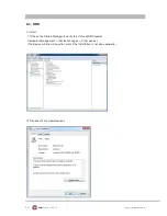
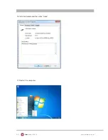
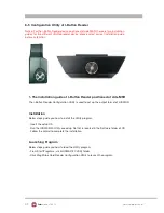
Страница 52: ...1 Install 1 1 Check the Device Manager to verify the status of RFID reader Computer Management Device Manager Other devices The device will show a question mark if the installation is not done properly 1 2 Double click to Update driver 6 4 RFID ...

Страница 53: ...53 www colormetric net Colormetrics P3300 1 3 Select Browse my computer for driver software 1 4 Click Browse to select file called HFF320U Driver FTD x64 And click Next 1 5 Install the driver ...

Страница 54: ...54 www colormetric net Colormetrics P3300 1 7 Restart the computer 1 6 Install complete and then click close ...

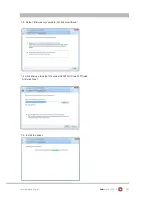
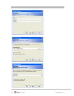
Страница 55: ...55 www colormetric net Colormetrics P3300 2 1 Double click to install 2 Install framework 4 0 2 2 Select I have read and accept the license terms And click Install ...

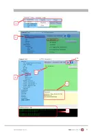
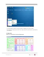
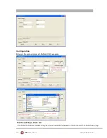
Страница 56: ...re setup required just double click the MP Studio exe The demonstration software can run either from CD or a copy on hard drive The GUI of software is shown in below picture and ready to use 3 Quick Start with Demonstration Software 3 2 Following steps as shown in below picture demonstration a simple usage in reading UID of ISO14443A card for quick understanding ...

Страница 57: ...57 www colormetric net Colormetrics P3300 ...

Страница 58: ... used to set up the output format of HID MSR 1 The installation guide of I Button Reader positioned at side MSR Below steps guide you how to install the Utility program Installation Insert the setup CD Run the HIDMSR 20 Utility exe setup file that is located in the Software folder of CD Follow the wizard to complete the installation Launching Program Below steps guide you how to load the Utility p...

Страница 59: ...rogram will detect the connected reader If detected all the input text boxes If the reader has not been connected to PC yet please connect the reader and then click Refresh to Configuration Below is the main window of i Button Utility program get connected ...

Страница 60: ...tton ID length request from 0 16 Output order 5 formats could be select at Attach Remove i Button ID 0 0 All 1 CRC ID 2 ID FC 3 ID 4 Disabled Update Settings Once complete the settings click Update to update the settings to connected HID MSR reader Save Settings To save the settings to a file click Save specify the file name and location to be saved Open Settings To load pre saved settings click O...

Страница 61: ... at bottom case and side MSR Installation Below steps guide you how to install the Utility program Insert the setup CD Run the Colormetrics i Button Utility exe setup file that is located in the Software folder of CD Follow the wizard to complete the installation 1 Setup IButton _V1 0 exe software ...

Страница 62: ...62 www colormetric net Colormetrics P3300 ...

Страница 63: ...r setup communication between software and iButton module The utility program will detect the connected reader If detected all the input text boxes will be enabled If the reader has not been connected to PC yet please connect the reader and then click Refresh to get connected ...

Страница 64: ...Colormetrics P3300 Configuration Below is the main window of i Button Utility program For the settings there are Prefix Suffix Defines the data string which you would like to append in front or end of the i Button key string ...

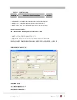
Страница 65: ... ES Define Start and End sentinel byte for the i Button ID string iButton data formate SS iButton 64 Bit Registration Number ES Length i Button ID length request from 0 16 Output order 4 formats could be select at Attach Remove i Button ID iButton 64 Bit Registration Number 8 Bit CRC 48 Bit ID 8 Bit FC DEMO SETUP OUTPUT OUTPUT DATA a ab00000003bdfa01 b ab00000003bdfa01 ...

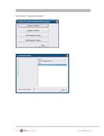
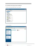
Страница 66: ...66 www colormetric net Colormetrics P3300 6 6 Installation and Testing of Smart Card Reader 1 Check smart card reader be detected by Device manager 2 Install the SCR driver ...

Страница 67: ...67 www colormetric net Colormetrics P3300 3 Run Setup exe 4 Click Yes ...

Страница 68: ...68 www colormetric net Colormetrics P3300 5 Restart systems 6 Check SCR reader in Device Manager ...

Страница 69: ...69 www colormetric net Colormetrics P3300 7 Run the testing program EZ100test 8 Conferm that SCR can be detected by the testing program the Start Testing ...

Страница 70: ...70 www colormetric net Colormetrics P3300 9 Follow dialog boxes displayed to remove and insert card 10 After finishing the testing the dialog box will show oK ...

Страница 71: ...TILITY SETUP Date and Time The Date and Time items show the current date and time on the computer If you are running a Windows OS these items are automatically updated whenever you make changes to the Windows Date and Time Properties utility WARNING Setting the wrong values in the sections below may cause the system to malfunction Make sure that the settings made are compatible with the hardware ...

Страница 72: ...72 www colormetric net Colormetrics P3300 7 1 Advanced Use the Advanced menu to configure the system for basic operation through the following sub menus ...

Страница 73: ...ot being used 1 Suspend Disabled Use the ACPI Sleep State option to specify the sleep state the system enters when it is not being used 2 S1 CPU Stop Clock DEFAULT The system enters S1 POS sleep state The system appears off The CPU is stopped RAM is refreshed the system is running in a low power mode 3 S3 Suspend to RAM The caches are flushed and the CPU is powered off Power to the RAM is maintain...

Страница 74: ...74 www colormetric net Colormetrics P3300 7 1 2 S5 RTC Wake Settings Enable or disable system wake on alarm event When enabled system will wake on the hr min sec specified ...

Страница 75: ...75 www colormetric net Colormetrics P3300 7 1 3 CPU Configuration Use the CPU Configuration menu to enter the CPU Information submenu or setup Intel CPU parameter ...

Страница 76: ...nge and or set the configuration of the SATA devices installed in the system 7 1 4 SATA Configuration Use the SATA Mode option to configure SATA devices as normal IDE devices Disable Disables SATA devices IDE Mode Configures SATA devices as normal IDE device RAID Mode Configures SATA devices as RAID device ...

Страница 77: ...ion Use the Configuration menu to change and or set the configuration of the internal graphics devices installed in the system DVMT Mode Use the DVMT Mode option to configure internal graphics device DVMT FIXED Memory Use the option to configure memory size of internal graphics device ...

Страница 78: ...Use the Legacy USB Support BIOS option to enable USB mouse and USB keyboard support Normally if this option is not enabled any attached USB mouse or USB keyboard does not become available until a USB compatible operating system is fully booted with all USB drivers loaded When this option is enabled any attached USB mouse or USB keyboard can control the system even when there is no USB driver loade...

Страница 79: ...79 www colormetric net Colormetrics P3300 7 1 7 IT8783F Super IO Configuration Use the Super IO Configuration menu to set or change the configurations for parallel ports and serial ports ...

Страница 80: ... Port Enabled Use the Serial Port option to enable or disable the serial port Change Settings Auto Use the Change Settings option to change the serial port IO port address and interrupt address Auto The serial port IO port address and interrupt address are automatically detected Disabled Disable the serial port Enabled Enable the serial port ...

Страница 81: ...81 www colormetric net Colormetrics P3300 7 1 8 Parallel Port Configuration Use the Parallel Port Configuration menu to configure the parallel port ...

Страница 82: ...82 www colormetric net Colormetrics P3300 7 1 9 H W Monitor The H W Monitor menu shows the operating temperature and fan speeds ...

Страница 83: ...trics P3300 7 2 Chipset Use the Chipset menu to access the Northbridge and Southbridge configuration menus WARNING Setting the wrong values for the Chipset BIOS selections in the Chipset BIOS menu may cause the system to malfunction ...

Страница 84: ...er option to select the graphics controller used as the primary boot device Select either an integrated graphics controller IGD or a combination of PCI graphics controller a PCI express PEG controller or an IGD Configuration options are listed below IGD Memory 64 M Use the IGD Memory option to specify the amount of system memory that can be used by the internal graphics device IGD PCI IGD PCI PEG ...

Страница 85: ...ion menu to configure the Southbridge chipset Serial Port 1 2 Voltage Select STD Select COM1 2 PIN9 Function and press Enter to setup COM 1 2 PIN9 function ITEM Option Descriptions COM1 PIN9 Function STD Default 5V 12V COM1 2 Pin9 select RING function COM2 PIN9 Function COM1 2 Pin9 select 5V 12V function ...

Страница 86: ...86 www colormetric net Colormetrics P3300 7 2 3 ME Subsystem Use the ME Subsystem menu to configure the Intel Management Engine ME configuration options ...

Страница 87: ... to configure system boot options Bootup NumLock State On Use the Bootup NumLock State BIOS option to specify if the number lock setting must be modified during boot up Quiet Boot Enabled Use the Quiet Boot BIOS option to select the screen display when the system boots ...

Страница 88: ...3300 7 4 Security Use the Security menu to set system and user passwords Administrator Password Use the Administrator Password to set or change an administrator password User Password Use the User Password to set or change a user password ...

Страница 89: ...89 www colormetric net Colormetrics P3300 7 5 Save Exit Use the Save Exit menu to load default BIOS values optimal failsafe values and to save configuration changes ...

Страница 90: ...an LCD screen A soft cotton cloth When cleaning the LCD screen it is important to use a soft cotton cloth rather than an old rag Some materials such as paper towels could cause scratches and damage the LCD screen Solution of water and isopropyl alcohol This solution can be used along with the soft cotton cloth Computer wipes Only use these if they specifically state on the package they are designe...

Страница 91: ...s encouraged to try to correct the interference by one or more of the following measures Reorient or relocate the receiving antenna Increase the separation between the equipment and receiver Connect the equipment into an outlet on a circuit different from that to which the receiver is connected Consult the dealer or an experienced radio TV technician for help Shielded interface cables must be used...

Отзывы: