background image


User Manual


www.colorlight-led.com                                    Version: V1.0                                    2015/11/26


V.


Parameter Configuration 

First of all, please make sure the software is in

 Classic Mode

 before setting. 

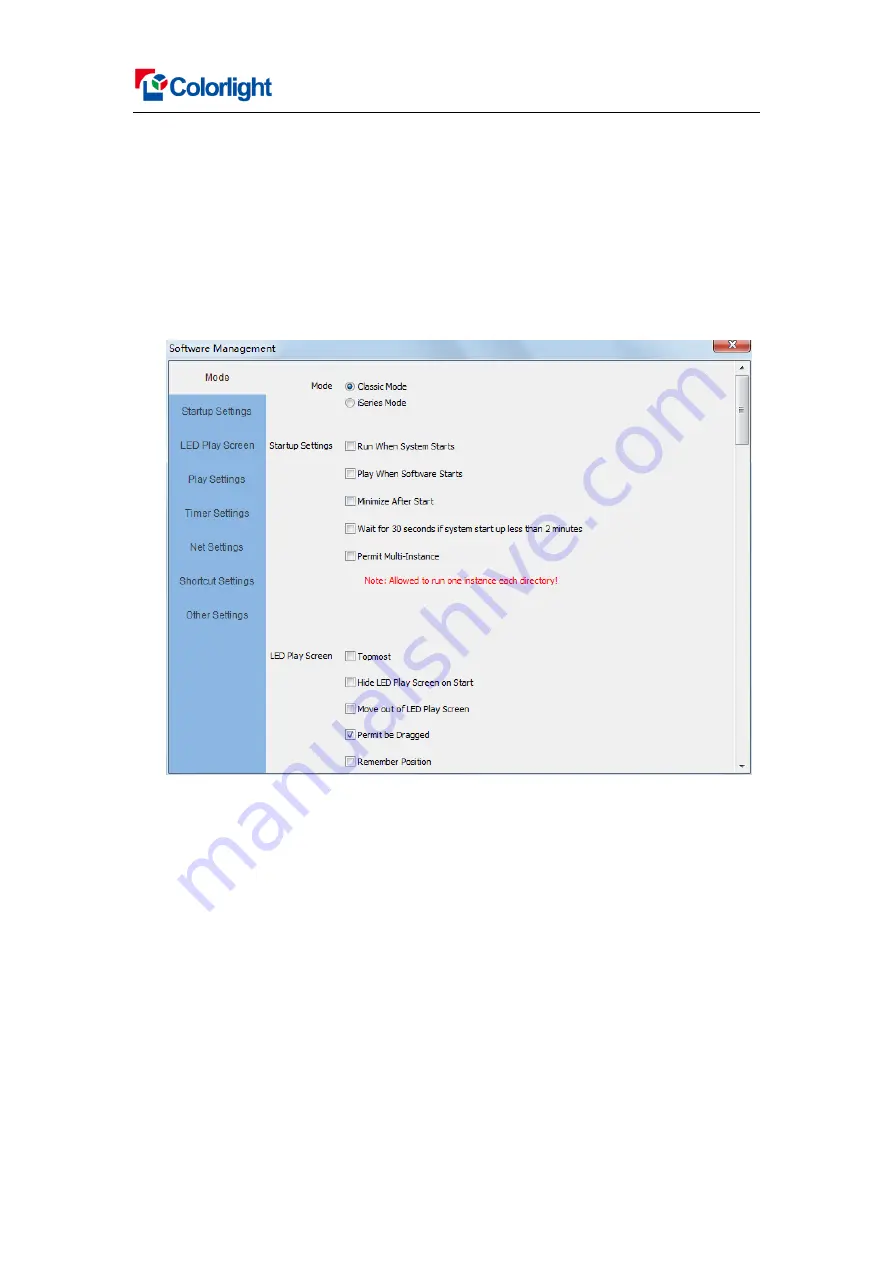
Click the “Setting” > “Software Setting” to enter the Software Management window 

(As shown in Fig.5-1), change the mode by using password: 168.


Fig.5-1 

5.1 Hardware Connection Check


Please make sure that the hardware connection correct and software in Classic 

Mode before setting. 

5.1.1 Detect Sender Cards 

Run software, c

lick the “Control” > “Screen Management” to enter the Screen 

Management window, the Sender Mode select 

“By Sender Card”, Click “Detect Sender 

Cards”, the sender cards information will show in the interface, (as shown in Fig.5-2 ) 

Please check the hardware connection if cannot detect sender cards. 


Содержание T7H

Страница 1: ...User Manual T7H Sender User manual Version V1 0 2015 11 26...

Страница 2: ...User Manual www colorlight led com Version V1 0 2015 11 26 Content I Product introduction 3 II Hardware 4 III Hardware Connection Diagram 6 IV Operating Environment 7 V Parameter Configuration 10...

Страница 3: ...he most commonly used synchronous system sender it is adopted the dual USB interfaces to realize high speed communication with PC and easy cascading between sender cards It supports wide working volta...

Страница 4: ...tput For output cascade signal to the next T7H 4 Cascade input For input cascade signal from the last T7H 5 Indicator lamp Indicate sender working state Red for power green for signal 6 Output port A...

Страница 5: ...input 11 Digital tube Show the brightness adjustment levels of the sender 12 Selection bottom Used for brightness adjustment and assisted selection 2 1 2 Indicator Light functions Red ON for power av...

Страница 6: ...em to input video according actual If you need to switch video input mode between HDMI and DVI signal can use HDMI and DVI cable to connect the computer and T7H at the same time 3 Control signal conne...

Страница 7: ...tion Adjustment mainly aims at total pixels of LED display complex playing program and whether playing HD video or not Please note that the PC s graphic resolution should be equal to or more than LED...

Страница 8: ...wn in Fig 4 2 Fig 4 2 How to change the mode there have different ways in different computer For example WIN 7 8 system and NVIDIA graphics cards please read the following settings ways The first way...

Страница 9: ...User Manual www colorlight led com Version V1 0 2015 11 26 Fig 4 4 Fig 4 5...

Страница 10: ...using password 168 Fig 5 1 5 1 Hardware Connection Check Please make sure that the hardware connection correct and software in Classic Mode before setting 5 1 1 Detect Sender Cards Run software click...

Страница 11: ...eiver Cards Select network port and click Detect Receiver Cards the software will automatic acquisition the Receiver Receiving card quantity for each network port of the sending card Please check cabl...

Страница 12: ...2 1 Sender Card Setting Software offers a variety of common resolution to choose and it also can be set up custom It should be note that the port maximum load capacity is 655360 pixels and the starti...

Страница 13: ...olorlight led com Version V1 0 2015 11 26 Fig 5 4 5 2 2 High Setting In Screen Management interface click High Setting to enter the High Setting Send Card interface the parameter can be set up accordi...

Страница 14: ...ng Adjust Brightness Based on Multi function Check it if you need multifunction s light sensor automatically adjusts the LED screen s brightness DVI Information The parameters automatically collect by...

Страница 15: ...pport arbitrary adjustment from 0 65536 level gray Indoor full color LED display adopt 4096 level gray Scan Method The method of high refresh frequency 2 means that scan gray firstly the refresh rate...

Страница 16: ...ht you will see led display mapping area Viewing from the front of led display As shown in Fig 5 7 Fig 5 7 2 Receiver Card Parameters Setting Configuration Receiver Receiving Card connection pattern f...

Страница 17: ...act and then the connection line will show Receiver Receiving card in the display mapping area As shown in 5 9 Fig 5 9 If some Receiver Receiving card manage different quantity of pixels from others s...

Страница 18: ...ards select port to send the parameter to receiver cards of this port load at this moment this port load all cabinets should display normally the picture between cabinets is not continuous but also as...

Отзывы: