background image


Page | 30  


VERVE LED 

 10. Head Cleaning 

Print Head is a delicate part which needs to be cleaned as per the recommended methods to have long 
life  and  to  ensure  consistent  print  quality.  Below  sections  give  recommended  steps  to  clean  the  Print 
Heads. 

Head Blotting and Purging 

Head  blotting  refers  to  the  process  in  which  the  head  surface  area  is  cleaned  with  the  help  of  cloth. 
Blotting removes ink drops adhering to the Print Head nozzle surface. Gently touch the surface of print 

head’s nozzle plate 

with recommended piece of cloth. One should make sure that the cloth is clean and 

soft. 

The Head Blotting process is shown in the image below: 


Fig 36: Cleaning the Print Head with a Piece of Cloth 

Perform these steps to clean the Print Head: 

Step 1: 

Open the Print Control Center. 

Step 2:

 Select the 

Maintenance 

menu. 

Step 3:

 Select the 

Carriage Lifter

 tab.  

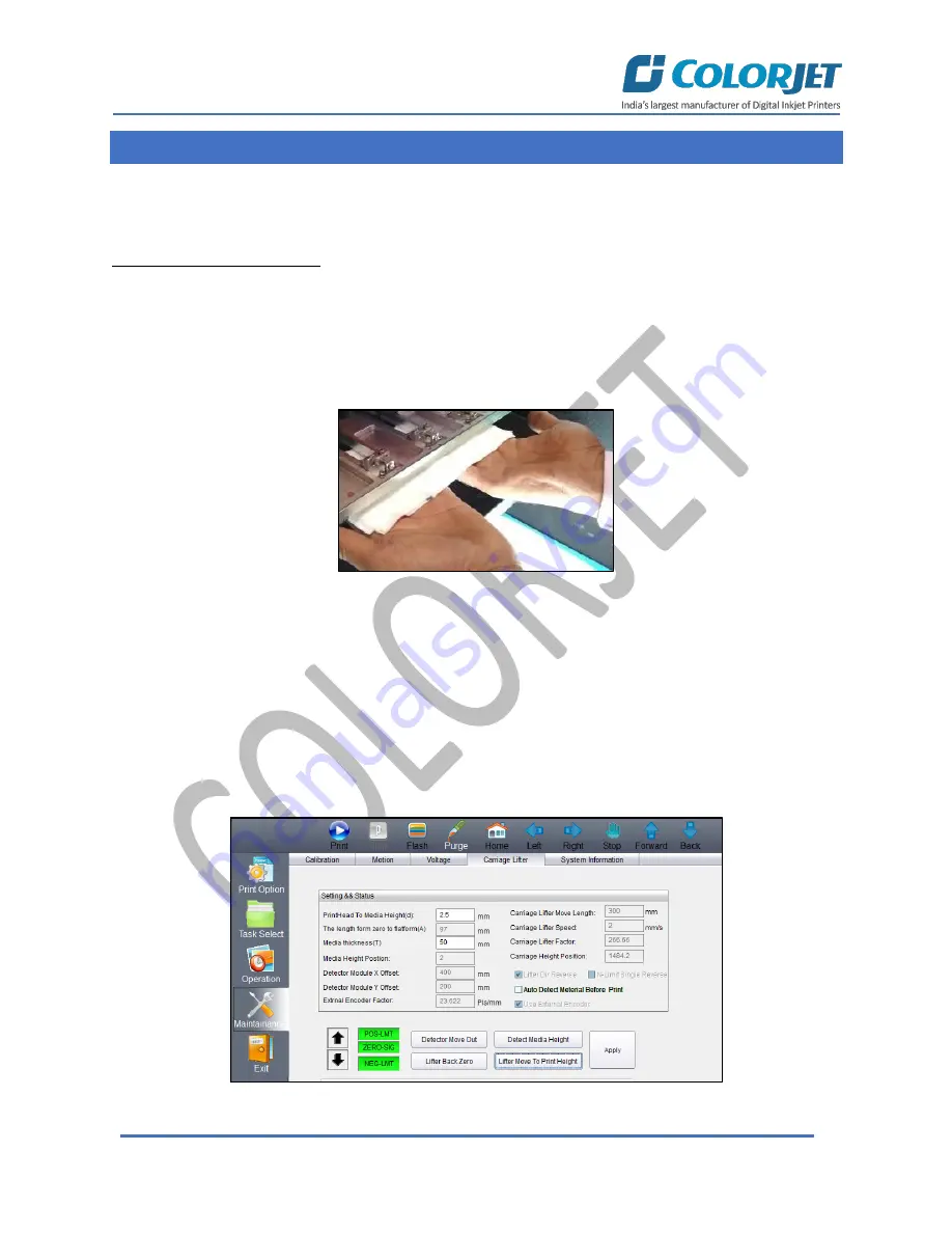
Step 4:

 Click on the 

Lifter Back Zero/Up Arrow icon

 button to lift up the carriage for blotting, as shown 

below: 


Fig 37: Lifting Up the Carriage 

Содержание VERVE

Страница 1: ......

Страница 2: ...3 machine without anyone else assistance The information provided in this document ensures its uniqueness and language quality For safe and proper use of the product please read this manual carefully...

Страница 3: ...illing 12 6 Main Menu Description 13 7 Print Control Center Operations 14 Print Option Menu 14 White and Varnish Settings 15 Layer Mode 17 Task Select Menu 18 DPI and Passes 19 Checking the Image Ink...

Страница 4: ...stem Maintenance 35 Ink Supply System Maintenance 35 13 Troubleshooting Guide 37 Printer Not Initializing 37 Printer Manager Not Showing READY 37 Print Stops in Between Printing 37 Print Margin is Shi...

Страница 5: ...es targeted audience is much familiar with the terminologies of printer and printing business Thus this document is designed to facilitate both types of users 2 Specifications VERVE LED VLR 2513 Print...

Страница 6: ...able 1 Different Parts of the Machine 1 Left UV Lamp 2 Negative Pressure ON OFF Knob 3 Right UV Lamp 4 Print Bed 5 UV Lamp Control Button 6 LED 7 Emergency Button 8 Bed Vacuum ON OFF Button Right UV L...

Страница 7: ...uick Access Buttons Display frequently performed actions like Print Stop Flash Purge Home Left Right Stop Forward and Back Error Messages Displays the system generated error messages Setting Carriage...

Страница 8: ...inting operations Step 2 Check Ink Level Step 3 Check Waste Ink Bottle Step 4 Release the Emergency button if pressed Step 5 Check water level in the Chiller Unit and fill it if required Step 6 Switch...

Страница 9: ...Print Bed Step 10 Switch ON the Print Bed vacuum by pressing the Bed Vacuum button available on the front left side of the machine as shown below Note a Carriage path must be obstacles free b Ensure t...

Страница 10: ...ssing the Lifter Back Zero button on the Carriage Lifter tab under the Maintenance menu Refer to Fig 11 Step 15 Press the Purging button Refer to Fig 11 and clean print heads using the tissue provided...

Страница 11: ...uum button available on the front side of the machine as shown below Fig 8 Turning ON the Bed Vacuum Button Step 3 Switch ON the required vacuum chambers by moving the Vacuum Chamber knob as shown bel...

Страница 12: ...ng steps to adjust the head height a Enter the X Offset value in the Detector X Offset to PrintPos field b Enter the Y Offset value in the Detector Y Offset to PrintPos field c After providing offset...

Страница 13: ...shown below Fig 12 The Main Ink Tanks Note Main tanks are equipped with ink level sensor which beeps once the ink level goes down Step 3 Fix the sub ink tank connectors to the ink refilling pins in th...

Страница 14: ...Maintainance Password Enable to feed and update the Maintainance Password This can only be done by the service engine Reset Origin Enable to move the carriage to the Home Zero Position Parameter Usin...

Страница 15: ...orbar Option Enable users to define the colorbar width distance from image distance between colors and colobar position White Color Settings Using the above screen user can make white color settings l...

Страница 16: ...e color is printed Full White will be printed completely all over the image Valid Image White color is printed same as the percentage of CMYK color in the selected image Invalid Image White color is p...

Страница 17: ...the percentage of CMYK color in the selected image After selecting the desired option for varnish color select the varnish thickness and curing in the Varn Thick and Varn Curing list boxes available...

Страница 18: ...ease the depth of ink layer select the desire option from the available list For example if the layer mode C W V is selected This means the first layer of Color CMYK is printed then White and Varnish...

Страница 19: ...k Select Screen Follow these steps to open and print a file Step 1 After opening the Task Select screen navigate to the location where the printable file is stored Refer to Fig 18 Step 2 Double click...

Страница 20: ...ser has to specify total count of images in X axis and Y axis as well as horizontal and vertical distance between images Ink Volume Specify the ink requirements of each color to print the selected ima...

Страница 21: ...ars as shown below Fig 21 Displaying the Image Color Ink Volume Screen In the above image user can easily estimate the ink requirements for the selected image Pre process Varnish Setting To pre proces...

Страница 22: ...e Open image file for printing Print Position Set print settings like speed print direction X origin and Y origin Status Issue test print command Opening an Image File Follow these steps to open an im...

Страница 23: ...shown below Fig 25 Setting the Print Position Note This option enables user to define printing direction like right left and bi direction Checking Printing Status Before giving the nozzle test user n...

Страница 24: ...lue of media thickness print head to media height and lifter height by verifying it Maintenance Menu The Maintenance menu is shown in the below Fig 28 Displaying the Maintenance Menu The Maintenance m...

Страница 25: ...has to provide the value of X and Y Move Length which defines the distance travelled while moving the carriage and gantry manually in a single click of an arrow key Refer to the marked area The Voltag...

Страница 26: ...age in the Up or Down position Additionally this tab also helps in detecting the media height The System Information tab is used to provide a complete set of information about the Print Control Center...

Страница 27: ...in Board This hardware key is required to run the printer and valid for certain time period When the time period is completed printer gets stopped and needs new password to start For new password user...

Страница 28: ...menu as shown below Fig 33 Selecting the Carriage Lifter Tab Step 3 Here we can also enter Print Head to Media Height in the given field Step 4 Enter Media thickness if required Step 5 Click on the De...

Страница 29: ...Page 28 VERVE LED Caution This functionality may not detect soft material Uneven surface may damage the print head...

Страница 30: ...s are performed simply by providing data in the given fields If print head height is altered then user needs to perform bi direction calibration For bi direction click on the Bi Dir Offset Refer to Fi...

Страница 31: ...drops adhering to the Print Head nozzle surface Gently touch the surface of print head s nozzle plate with recommended piece of cloth One should make sure that the cloth is clean and soft The Head Blo...

Страница 32: ...printing position Refer to Fig 36 Note Please strictly follow the below mentioned instructions Avoid using the same cloth to clean the Print Head Cleaning with dry and inferior quality tissue paper wi...

Страница 33: ...g Head spraying should be performed to avoid mixing of colors and also may open few blocked nozzles To perform head spraying click on the Flash button available on the Right Panel as shown below Fig 3...

Страница 34: ...Switch OFF the bed vacuum by clicking on the Bed Vacuum button as shown below Fig 39 Switch OFF the Bed Vacuum Step 2 Move the carriage over the print bed and bring down the carriage to the minimum po...

Страница 35: ...ng the OFF button as shown in the below image Fig 41 Switch OFF the Chiller Unit Step 4 Turn off the ink valves Step 5 Switch OFF the printer from the main power Step 6 Turn Off the main switch After...

Страница 36: ...able environment Prevent the object or human body with static contact to the print head Print head nozzles should be kept clean dust free and also prevent from oxidation Maintenance of Machine Motion...

Страница 37: ...Page 36 VERVE LED Check for damages on ink tubes Check Ink impurities in the ink tanks as this will affect the ink supplying...

Страница 38: ...pped file is having error Media is finished Print Margin is Shifting or Junk Printing Encoder scale is having ink stains Encoder sensor is not clean Pulley or belt is slipping Data cable is faulty Pri...

Страница 39: ...nk tanks UV Lamp Not Working UV lamp is aged Check the power of the UV Controller System Check the power of the Chiller unit Check the coolant level Check the coolant pipe if cut or bend UV Ink is not...

Страница 40: ...Page 39 VERVE LED...

Отзывы: