9
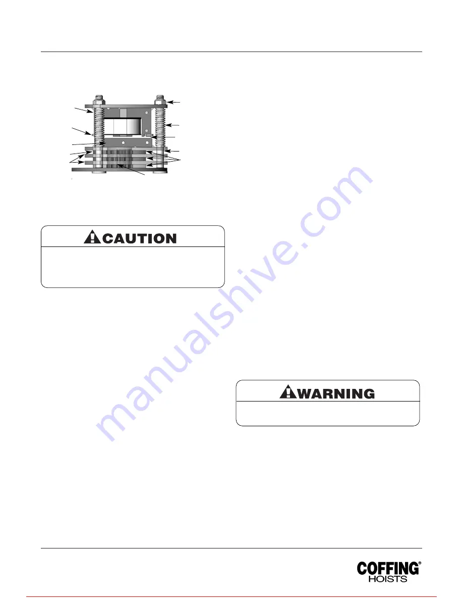
3. Adjust gap by adjusting the 3 locknuts “F” and checking with
a feeler gauge to be sure gap is the same on both ends of
the solenoid.
4. Adjustment is now complete and the brake properly set.
Replace the electrical cover, reconnect the power supply,
and check lifting motor brake action.
WIRING
Refer to Figures 7A, 7B and 7C.
Single-phase units (115/230V) are wired for 230V and
230/460V-3 phase units are wired for 230V unless otherwise
specified when ordering. Lifting motors ordered with other
3-phase voltages are single-voltage only. Conversion of dual
voltage units can be done simply and quickly as follows.
1. DISCONNECT LIFTING MOTOR FROM POWER SUPPLY
and remove electrical cover.
2. On 230/460V-3 phase units converting to 460V requires
removing the C1, C2 and C3 jumpers as shown on the
wiring diagram 983CE2100-000. The motor leads T4, T5 and
T6 are then connected to the blocks as shown. Save the
three jumper wires for conversions back to 230V. One of the
transformer leads H2 (230V) and H4 (460V) is connected to
the contactor as shown depending on the voltage.
On 115/230V-1 phase units, connections are only modified
at the terminal blocks as shown on wiring diagram
981CE0100-000.
3. Make sure that all of the screw clamps on the contactor and
terminal blocks are tightened. Tug on the wires to ensure
they are securely connected.
4. Check the operation of the lifting motor, ensuring that the
direction of travel is correct (See INSTALLING LIFTING
MOTOR, page 5).
IMPORTANT: Always refer to the wiring diagram located on the
inside of the electrical cover or Figures 7A, 7B and 7C when
performing electrical repairs. Make sure all terminals are securely
fastened and check for damaged insulation. It is also imperative
that the power circuit has conductors of adequate size.
LUBRICATION
Refer to Figure 9.
Proper lubrication is necessary to ensure a long and reliable
lifting motor life. Refer to the following and the
RECOMMENDED LUBRICATION SCHEDULE for lubrication
points, type of lubricant, and frequency of lubrication.
Load Chain
Clean the load chain with acid-free solvent and coat with new
SAE 90 gear oil. Wipe excess oil to prevent dripping. Never
apply grease to the chain.
Gearing
The gearbox of this lifting motor is filled at assembly with 1½
pints of SAE 90 EP gear oil. To check oil level, hang the unit by
the suspension hook (the unit and decals will be upside down)
and remove the oil level check plug. With the lifting motor
hanging level, the gear oil should be even with the hole.
Bearings
All bearings except hook and idler sheave bearings are
lubricated at the factory and should not require additional
lubrication. Noisy or worn bearings should be replaced.
Limit Switch Shaft
Remove any dirt accumulation and spray with a general
purpose lubricant.
Hook Bearing
Apply a few drops of new SAE 30 gear or motor oil around the
edge of the bearing.
Idler Sheave Bearing (Bushing)
Disassemble load block and apply a light coat of NLGI #2
grease, or equivalent, inside of bearing.
NOTE: If lifting motor is used in an atmosphere containing
abrasive dust, frequent cleaning and oiling may be necessary.
LIFTING MOTOR REPAIRS
NOTE: If you do not have an experienced mechanic to do your
repair work, we recommend that you send your lifting motor to
an approved service station for repairs. Use authorized repair
parts only.
1. For major repairs or when the lifting motor is to be sectioned
in the suspension area, it will be necessary to move the
lifting motor to a workbench or table.
2. For repairs which can be done by removing the electrical
cover only, the lifting motor need not be moved. Lowering the
lifting motor to a convenient working level is desirable.
The following repair instructions will help you in understanding
repair procedures, when related to the Replacement Parts List
starting on page 16. For clarity these are broken down into areas.
Be sure the bottom of the armature does not bear
against the splined adapter “H”. As adjustments are
made, the built-in clearance will be reduced. When
this clearance is gone REPLACE BRAKE DISCS.
Minimum allowable disc thickness is .162". See
Figure 13 for further illustration.
Remove load and disconnect lifting motor from
power supply before starting to do any repairs or to
take any sections apart.
Country Club Road
P.O. Box 779
Wadesboro, NC 28170 USA
TEL: (800) 477-5003
FAX: (800) 374-6853
Figure 4 — Brake Assembly
Gap
F
G
X
B
E
A
X
D
H
C
For more information contact: Sievert Crane and Hoist, (708) 771-1600, [email protected], www.sievertcrane.com


