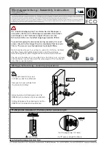
MODEL 520/525 INSTALLATION INSTRUCTIONS
Model 520/525 is a complete locking unit with all the parts necessary for a
new installation, or the total replacement of an existing lock.
IMPORTANT The mortice lock provided (fig. 2) has features which are not found in most other locks
and so it is recommended that you familiarise yourself with them as follows:
A. When necessary the hand
of the latchbolt can be
changed by removing the
three screws holding the
faceplate to the lockcase
and reversing the latchbolt.
B. Put the key in the cylinder
and insert it centrally into
the lockcase. Fix it in
position with the long bolt
through the faceplate. It
should now be possible to
project and retract the
deadbolt with the key, and
also to retract the latchbolt.
C. The square latchbolt
follower is in 2 parts: the
inside ‘panic function’
follower will retract the
latchbolt and also the
deadbolt when it is
projected. The effect of
this is to ensure that it is
not possible to accidentally
lock someone in a room
because the deadbolt is
projected. The outside
follower will always retract
the latchbolt whenever the
lever handle is depressed
after a correct code is
entered, but it will not
retract the deadbolt.
The hand of the ‘panic
function’ is determined as
follows: the grub screws
on the split follower facing
the code side must be
removed. This prevents
the outside handle
retracting the deadbolt.
NEVER remove grub
screws from both sides at
the same time.
All door locks should be
installed with a degree of
precision to ensure that all
components are horizontally
and vertically accurate in
relation to each other, and in
relation to the door.
Do not install the lock where
it will involve cutting into a
joint between the door stile
and a mid-rail.
step 8
Fitting the strike plate.
NB: The plunger beside the
latchbolt deadlocks it to
protect against manipulation
or ‘shimming’. The strike plate
must be accurately installed
so that the plunger CANNOT
enter the aperture when the
door is closed, even if it is
slammed shut.
Position the strike plate on
the door frame so that it lines
up with the flat of the
latchbolt, and NOT the
plunger. Mark the positions of
the fixing screws, and draw
around the aperture of the
strike plate. Chisel out the
aperture 15mm deep to
receive the latchbolt. Fix the
strike plate to the surface of
the frame using only the top
fixing screw. Gently close the
door and check that the
latchbolt enters the aperture
easily, and is held without too
much ‘play’. When satisfied,
draw around the outline of the
strike plate, remove it and cut
a rebate to enable the
faceplate to lie flush with the
surface. Re-fix the strike plate
using both screws.
step 9
Apply the front and back
plates, with the neoprene
seals in position, against the
door, over the protruding
ends of the spindle.
step 10
Fix the two plates together
using the socket head bolts,
starting with the top fixing.
Ensure that the two plates
are truly vertical and then
tighten the bolts using the ‘T’
shaped Allen key. Do not use
excessive force.
step 11
Before closing the door,
enter the code and ensure
that the latchbolt will retract
when the lever handle is
depressed. Now check the
operation of the inside lever
handle. If there is any binding
of the handles or latch then
loosen the bolts slightly and
reposition the plates slightly
until the correct position is
found, and then re-tighten
the bolts.


