Technical Manual
Page 14
CODEL
OPS.109
Issue : B
Rev. : 1
Date : 23/10/13
Doc. i/d : 0109/6
Ref. : 090028
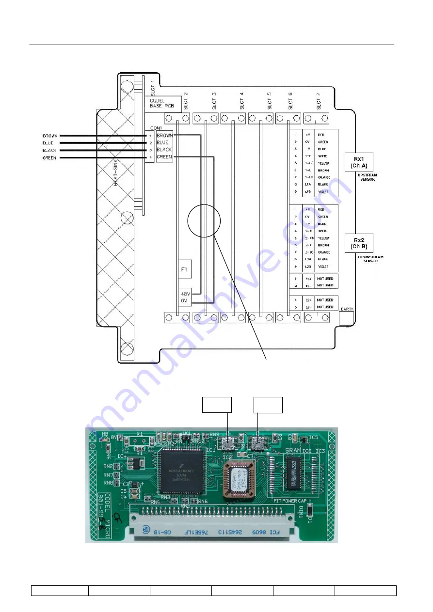
Figure 7 : Details of SPU Wiring
Figure 8 : SPU Microprocessor Card
SW2
SW1
To DDU
Keep links in place
Страница 1: ...TECHNICAL MANUAL SmartCem Emissions Monitoring System Model V CEM5100 Flow Monitor CODEL International Ltd Station Building Station Road Bakewell Derbyshire DE45 1GE United Kingdom t 44 0 1629 814 35...
Страница 2: ...CODEL OPS 109 Issue B Rev 1 Date 23 10 13 Doc i d 0109 6 Ref 090028...
Страница 3: ...itself and for the rest of the industry All development and design work is carried out in house by experienced engineers using proven state of the art CAD and software development techniques while st...
Страница 4: ...CODEL OPS 109 Issue B Rev 1 Date 23 10 13 Doc i d 0109 6 Ref 090028...
Страница 5: ...b Pipes and Mounting Flanges 8 4 3 2 Air Purges 9 4 3 3 Transducer Heads 10 4 3 4 PSU SPU 10 4 3 5 DDU 11 5 Electrical Connections 12 5 1 Installation and Connection of Cables 12 5 2 Connection Schedu...
Страница 6: ...malisation 24 7 8 Diagnostic Mode 24 7 8 1 Detector Levels 24 7 8 2 System Gain 24 7 8 3 Displacement 25 7 8 4 Flow Data 25 7 8 5 Calibration Data 25 7 8 6 Fault Condition 26 7 9 Set up Mode 26 7 9 1...
Страница 7: ...elow are used throughout these instructions and are intended to ensure your safety while carrying out installation operation and maintenance procedures Please read these instructions fully before proc...
Страница 8: ...Technical Manual CODEL OPS 109 Issue B Rev 1 Date 23 10 13 Doc i d 0109 6 Ref 090028...
Страница 9: ...ance costs and potential unreliability The CODEL Model V CEM5100 Gas Velocity Monitor utilises an infrared cross correlation technique that requires no contact with the flue gases The method used rese...
Страница 10: ...C power from the Power Supply Unit PSU Signals from the two transducers are processed and correlated to derive the transmission time of the gas flow from the first transducer to the second and thus co...
Страница 11: ...gas flow to carry the vortices from the first detector to the second The V CEM5100 uses a cross correlation technique to measure this time displacement and hence the flow The two signals from the inf...
Страница 12: ...for a fixed number of time delay intervals to derive the correlogram For example if the set of data above where each signal a t and b t each comprise a square pulse resulting in a triangular shaped co...
Страница 13: ...ero time delay and the 256th element corresponds to 255 time delay increments Hence if a DATA RATE of 1ms is selected the 256th element corresponds to a time delay of 255ms Displacement is the point o...
Страница 14: ...0 o C to 50 o C PSU SPU DDU Power Requirements PSU 90 264V AC max 50 60Hz V CEM 48V DC from PSU Air Purge Consumption 1 l s 1 bar compressed air dry to 20 C clean better than 10 m Analogue Outputs DDU...
Страница 15: ...ld be mounted local to the transducers and is supplied with 10m of cable as standard The transducers need to be mounted so that a maximum pathlength is achieved whilst maintaining an acceptable confid...
Страница 16: ...including eye protection and protective gas mask should be worn The transducer heads should be mounted vertically above each other and no more than 1m apart Construct the mounting assemblies by weldin...
Страница 17: ...air purge Customers may specify their own blower it should be able to deliver 5 litre second about 10cfm against the working pressure of the duct CODEL can specify a blower if required The flange of...
Страница 18: ...r captive screws The case is then secured to a firm support by use of the four mounting holes one in each corner of the case Since the mounting holes are located outside the seal of the case it is not...
Страница 19: ...o a firm support by use of the four mounting holes one in each corner of the case Since the mounting holes are located outside the seal of the case it is not necessary to seal the mounting holes after...
Страница 20: ...efore installation Power cables customer supply should be installed separately using different routes if possible to reduce the risk of cross interference Leave sufficient free end length to make fina...
Страница 21: ...Technical Manual Page 13 CODEL OPS 109 Issue B Rev 1 Date 23 10 13 Doc i d 0109 6 Ref 090028 Figure 6 Connection Schedule...
Страница 22: ...Technical Manual Page 14 CODEL OPS 109 Issue B Rev 1 Date 23 10 13 Doc i d 0109 6 Ref 090028 Figure 7 Details of SPU Wiring Figure 8 SPU Microprocessor Card SW2 SW1 To DDU Keep links in place...
Страница 23: ...Technical Manual Page 15 CODEL OPS 109 Issue B Rev 1 Date 23 10 13 Doc i d 0109 6 Ref 090028 Figure 9 DDU Microprocessor Card Address switch...
Страница 24: ...sists of the following procedures Power Supply Voltage 85V to 264V AC Apply Power Switch the power on and observe the power supply rail indications Alignment Align transducers using the integral adjus...
Страница 25: ...ault condition or channel 1 saturation condition occur it means that the detector levels are outside the range of the AGC system and the gain of the transducer heads should be increased or reduced res...
Страница 26: ...eceived by the two optical transducers It is important to ensure that the signal levels from the two transducers are correct There are two levels of gain adjustment one a hardware gain adjustment in t...
Страница 27: ...be the same serial comms address DDU microprocessor card rotary switch SW1 serial comms address SPU microprocessor card rotary switch SW1 SW2 0 7 2 Operating Modes The instrument has four modes of op...
Страница 28: ...mode 7 3 2 Arrow Keys Pressing the and keys will do one of two things depending on the position in the program It will increase or decrease the displayed value If the key is held down it will scroll...
Страница 29: ...NTENDED TO BE REPRESENTATIVE ONLY 7 5 1 Measurement Mode From this mode of operation the averaging time of the displayed flow may be altered to one of the other averaging stacks and the flow measureme...
Страница 30: ...o the upstream transducer by the computed delay The monitor then performs its normal correlation process on the value This computed flow value should be the same as the value entered for the low cal a...
Страница 31: ...o be the upstream detector Channel A is always defined as the upstream or lead transducer Depending on the wiring channel A may be either transducer 1 or transducer 2 It is necessary to select the cha...
Страница 32: ...or levels for both channels will be displayed 4 DIAGNOSTICS Detector Outputs The two detector levels channel A channel B are displayed as instantaneous rms values in the left hand display and smoothed...
Страница 33: ...easurement points is determined by Time displacement t x data rate ms The correlation coefficient is an assessment of the quality of data Correlation coefficient Ref val min val x 100 Ref val Coeffici...
Страница 34: ...prevent any unauthorised changes the user must enter a four number code before the mode can be entered After this mode has been selected the instrument will suspend its operation and the Data Valid LE...
Страница 35: ...R Repeat this procedure for the four numbers If the code is correct after the ENTER key is pressed on the last digit then the sequence will be continued if it is not correct the instrument will return...
Страница 36: ...minute intervals 5 SET AVERAGES mins 60 Set the hours averaging stack to the required value This is limited to within 1 to 24 hours in 1 hour intervals 5 SET AVERAGES hours 24 Set the days averaging...
Страница 37: ...d The current value will be displayed for 1 second when this option is entered The display then defaults to zero thus the span value must be re entered for the unit to function correctly 5 CONFIGURE O...
Страница 38: ...ment 7 9 4 Configure O P2 The analogue current loop output terminals 25 26 is set up from this mode Press the ENTER key while this display is shown to select it then press the and keys to step through...
Страница 39: ...desired option is displayed press the ENTER key 6 9 3 6 Set mA Output This is set at the factory and should not be altered without due consideration From this option the current levels of the analogu...
Страница 40: ...Hi Level 20m sec Select the level 1 digit at a time using and and set by pressing ENTER 7 9 6 Alarm Lo The operation of the volt free contact alarm output terminals 15 16 17 is configured from this m...
Страница 41: ...ent set up 7 9 7 2 Units The system operates in metric units to provide output data in m sec 5 PARAMETERS Units metric 7 9 7 3 Detector Separation Distance The current value entered for separation wil...
Страница 42: ...ment 5 PARAMETERS Data rate 1 0ms Auto Ranging Switching the data to auto enables the monitor to select automatically the appropriate data rate for the flow being measured 7 9 7 6 Channel Switch It is...
Страница 43: ...ds 17 Scroll seconds using 7 9 8 Calibrate The way in which the calibration is initiated and in which calibration data is outputted is configured here A manually initiated calibration can also be trig...
Страница 44: ...a calibration 5 CALIBRATE Calibrate Enter 5 Lo flow 025 Cal in progress End when count 0 5 Hi flow 023 Cal in progress End when count 0 Config Cal sets parameters for a remote timed activated calibra...
Страница 45: ...t status input terminals 28 29 in the signal processor Configure this option by selecting YES or NO to Initiate via Plant Status Cal Alarm The alarm Hi relay can be reconfigured to act as a cal in pro...
Страница 46: ...socket head screws and cleaning each window with a clean soft dry cloth Clean the internal surfaces of the mounting tubes to remove any build up of dust or ash It is estimated that window cleaning sho...
Страница 47: ...y modes and the initial variable values shown in Section 7 DDU Operation will act as a guide to determine correct performance This can be done at any time without interrupting or disturbing the analog...
Страница 48: ...9 Figure 4 PSU SPU Mounting Details 10 Figure 5 DDU Mounting Details 11 Figure 6 Connection Schedule 13 Figure 7 Details of SPU Wiring 14 Figure 8 SPU Microprocessor Card 14 Figure 9 DDU Microprocess...