


8
2009 Audiovox Electronics Corporation. All rights reserved.
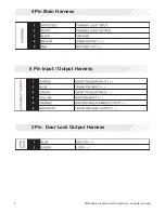
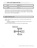
2 Pin Lock Output Harness
1
BLUE
UNLOCK ( - )
2
GREEN
LOCK ( - )
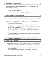
The door lock / unlock outputs are designed to control several different types of
systems which may require additional parts. Please review the wire and location
chart to see which type of door lock system is in your vehicle. The most common
types are shown in the following diagrams.
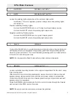
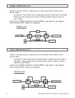
Negative Switching Locks
All Door Lock and Unlock: Locate the lock / unlock wire at the vehicle’s lock /
unlock switch.
Verification: These wires will register ground when the Lock and Unlock
switches are activated.
Connect the GREEN and BLUE wires shown in the diagram below.
Lock
Unlock
Vehicle Door Lock
Control Relays
GREEN (-) Lock Output
BLUE (-) Unlock Output
Negative Locks: