Page 2 of 4
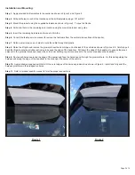
Figure 1
Installation and Mounting:
Step 1.
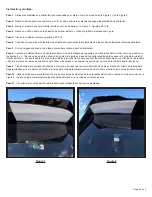
Apply provided drill templates to the spoiler as shown in Figure 1 and Figure 2.
Step 2.
Drill pilot holes in each of the locations per the drill templates using a 1/8” drill bit.
Step 3.
Mount the product using the supplied hardware as shown in Figure 3. Torque to 20in-lbs.
Step 4.
Drill a pilot hole in the remaining hole location using the mounted product as a guide.
Step 5.
Insert the remaining hardware and torque to 20in-lbs.
Step 6.
Consult the factory service manual to remove the fasteners from the vertical side sections of the spoiler.
Step 7.
Notch a small area on each side to route the cable through the plastic.
Step 8.
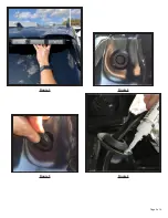
Raise the lift gate and remove the grommet near the door hinge on both sides of the vehicle as shown in Figures 4-5. Carefully pull
back the lift gate water seal rubber extrusion to expose the edge of the headliner. Pull down the edge of the headliner to expose the areas
adjacent to the grommet holes and loosen the corner trim molding to get more access to the corner area above the headliner.
Step 9.
Route each harness around the edge of the spoiler and feed the harness end through the grommet hole. Do this while guiding the
harness end along the edge of the headliner to the area near the center of the vehicle.
Step 10.
Apply adhesive supplied with the kit to the outer edges of the harness grommets as shown in Figure 6. Install and fully seat the
harness grommets in their respective holes.
Step 11.
Refer to product specific manual to form the proper connections.
Figure 2

