


7
Options & Specification
AS-839 / AS-847 / AS-10
AS-10/ AS-847 Size:
47¼" L, 4¼" W, 2¾" H
AS-839 Size: 39 1/4"L, 3 1/4" W, 2 3/4" H
Weight: 10 lb
The following are optional features that may or may not be included in your control head depending upon which
model you've purchased.
"Fast Speed" Mode:
Pushing the button marked "Fast" will cause each of the 4 patterns of the ArrowStik
®
to
operate at a faster rate, with the same amount of light intensity.
"Dim" Mode:
Pushing the button marked "Dim" will cause each of the 4 patterns of the ArrowStik to operate at
a lower intensity level. This is for use during night operation when 100% intensity is too much, or
daytime use when current draw needs to be reduced.
"Aux" mode:
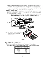
Pushing the button marked "Aux" will activate the control head relay. This will 12Vdc to
the terminal marked "Aux Output" in Figure 7. The LED on the front panel will light indicating that
the auxillary switch is activated. This auxiliary output is limited to 12Amps at 12.8 Vdc nominal.
External Flash Operation
Connect the "External Flash" input of the 7 position connector to +12 Vdc through a user supplied switch,
as shown in Figure 7. When this switch is closed, the ArrowStik will operate in the "Flash" mode, unless
another traffic directing pattern is already selected.
AS3P SECTION SPLIT ARROWSTIK & ASSP 4 SECTION SPLIT ARROWSTIK
SUPPLEMENTAL INSTRUCTIONS
Following are supplemental instructions for the model ASSP and AS3SP split ArrowStik
systems. This unit
requires the use of a special control box (S81014).
1) Mount each half of the split ArrowStik to the vehicle according to the "Installation and Mounting" section of
the user manual. Be sure to mount the unit marked "Driver" on the drivers side of the vehicle and the unit
marked "Passenger" on the passenger side of the vehicle. The cable should exit on the OUTBOARD side
of each unit.
2) Route the cable for each half of the ArrowStik through the vehicle to the location of the control head. Be sure
to leave the driver and passenger designations on each cable for proper wiring of the unit in the steps that
follow.
3) Refer to the "Wiring instructions" section of this user instruction manual, page 5. Beginning with the
cablemarked "Driver", connect each of the colored wire as shown in Figure 7, to the control head: however
DO NOT USE THE RED/WHITE, BROWN OR ORANGE WIRES in this cable. Cut these wires back to the
black jacket of the 7 wire cable.
4) With the cable marked "Passenger", connect each of the colored wires, as shown in Figure 7 of the user
manual, to the control head: DO NOT USE THE RED/WHITE, YELLOW OR BLUE WIRES in this cable. Trim
these wires back to the jacket of the 7 wire cable.
5) Complete the wiring and installation of the ArrowStik and control head according to the user instruction
manual.
Maintenance
The ArrowStik
requires minimal routine maintenance. Occasional cleaning of the lens is all that is required to
sustain maximum light output. Water or
Code 3
®
lens polish and a very soft cloth is needed for cleaning. The plastic
scratches easily, so cleaning is recommended only when necessary. The lens should not be removed at any time
.
!
The lamp bracket assembly is at +12Vdc/ +24Vdc. Power must be disconnected for
maintenance.
WARNING!
Lamps are extremely hot! Allow to cool completely before attempting to remove. Gloves and
eye protection should be worn when handling halogen lamps as they are pressurized and
accidental breakage can result in flying glass.
!
WARNING!
Содержание ARROWSTIK AS-10
Страница 10: ...FIGURE 10 7 6 1 9 2 3 4 11 12 13 10 14 16 5 15 8 10...
Страница 11: ...Notes 11...


