


5
5. Route a 20 gauge wire from the first position of the ArrowStik
®
control head plug to the +12Vdc (positive)
of the battery. Use a 5 amp fuse or breaker to protect the control head from over current conditions.
6. Check all connections for frayed or shorted wires. Insert the plug back into the ArrowStik control head.
7. Connect the red and red/white wires of the seven (7) wire cable to the +12Vdc (positive) of the battery
through a user supplied 20 amp fuse or breaker. If the red and red/white wires are terminated at the
controller, use a 12 gauge wire and heavy duty connector to connect the wires.
External Flash Wiring
Connect the second position of the control head plug to the user supplied switch with 20 gauge wire, use the
decal on the back of the controller as a guide. Route the switch positive lead to the +12Vdc battery (positive).
Use a 5 amp fuse or breaker for the circuit.
DELUXE
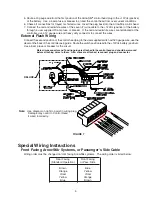
Special Wiring Instructions
Front Facing ArrowStik
®
Systems, or Passenger's Side Cable
Wiring order must be changed on front facing ArrowStik systems. The wiring order is listed below:
Rear Facing
(Standard Operation)
Brown
Orange
Violet
Yellow
Blue
Front Facing
or Pass. Side
Blue
Yellow
Violet
Orange
Brown
Male crimp connector and 7 position plug are attached to the control head and should be removed
before attaching wires to them. After wires are attached, reconnect plug and connector.
FIGURE 7
Note:
Use diagram on right to assist in wiring plug.
Damage may occur to Control Head
if wired incorrectly
.
"OPTIONAL"
Содержание ARROWSTIK AS-10
Страница 10: ...FIGURE 10 7 6 1 9 2 3 4 11 12 13 10 14 16 5 15 8 10...
Страница 11: ...Notes 11...