10
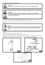
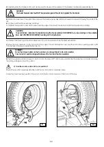
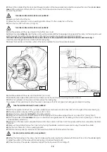
First use handle (19, Fig. D) to tip the arm to this position.
1)
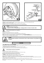
Move the joystick (8, Fig. C) up (a): the spindle carrier arm (2, Fig. A) should lift; move the joystick down (b): the arm should lower.
DANGER!
When the spindle carrier arm is lowered, there is always a potential for crushing anything in its
movement range. Always work from the position given in the instructions keep well out of the working
range of the various moving arms.
Move the joystick towards the left (c): the tool carriage and the mobile platform (13, Fig. D) should move towards the spindle (3, Fig. A);
move the joystick towards the right (d) the carriage and platform should move away from the spindle.
2)
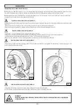
Turn switch lever (9, Fig. C) towards the top: the spindle arms (3, Fig. A) should open; move the lever down and the spindle arms
should close.
3)
Depress the right pedal (10, Fig. C): the spindle (3, Fig. A) should turn clockwise; depress the left pedal: the spindle should turn counter
clockwise.
DANGER!
When the spindle arms open or closed, there is always a potential for crushing anything in their movement
range. Always work from the position given in the instructions keep well out of the spindle’s working
range.
CAUTION!
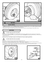
Do not move your face close to the tool carrier arm when you release it to tip it as needed.
D
C
E/1
18
14
1
19
15
4)
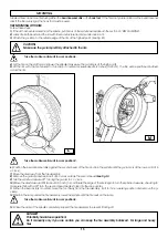
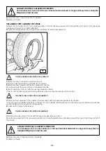
Check to be certain the hydraulic circuit is working propenly:
- move switch lever (9, Fig. C) towards the top until the spindle arms are fully extended.
- hold the switch lever in this position (top) and check if the pressure shown on the gauge on the swivel fitting is 1,885 PSI (130 bar)
±
10%.
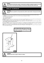
If the pressure shown in not as indicated here, DO NOT USE the tire changer and call your nearest Service Center.
17


