


IOM - DIY Heat Pump Series
25
www.coastair-ac.com
The size of the power supply cable, signal
cable, fuse, and switch needed is determined
by the maximum current of the unit. The
maximum current is indicated on the nameplate
located on the side panel of the unit. Refer to
this nameplate to choose the right cable, fuse,
or switch.
NOTE:
In North America, please choose the
right cable size according to the Minimum
Circuit Ampacity indicated on the nameplate
of the unit.
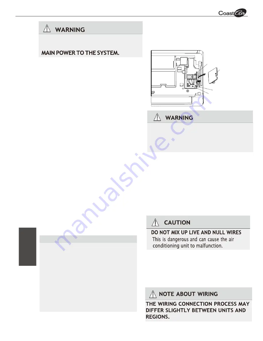
1.
O
pen front panel of the indoor unit.
2.
Using a screwdriver, open the wire box cover
on the right side of the unit. This will reveal
the terminal block.
Step 6: Connect signal cable
The signal cable enables communication between
the indoor and outdoor units. You must first
choose the right cable size before preparing it for
connection.
Cable Types
•
Indoor Power Cable
(if applicable):
H05VV-F or H05V2V2-F
•
Outdoor Power Cable:
H07RN-F or H05RN-F
•
Signal Cable:
H07RN-F
NOTE
: In North America, choose the cable type
according to the local electrical codes and
regulations.
Terminal block
Wire cover
Screw
Cable clamp
3.
Unscrew the cable clamp below the terminal
block and place it to the side.
4.
Facing the back of the unit, remove the plastic
panel on the bottom left-hand side.
5.
Feed the signal wire through this slot, from
the back of the unit to the front.
6.
Facing the front of the unit, connect the wire
according to the indoor unit’s wiring diagram,
connect the u-lug and firmly screw each wire
to its corresponding terminal.
7.
After checking to make sure every connection
is secure, use the cable clamp to fasten the
signal cable to the unit. Screw the cable clamp
down tightly.
8.
Replace the wire cover on the front of the
unit, and the plastic panel on the back.
CHOOSE THE RIGHT CABLE SIZE
BEFORE PERFORMING ANY ELECTRICAL
OR WIRING WORK, TURN OFF THE
In
do
or
U
n
it
In
st
all
at
io
n
ALL WIRING MUST PERFORMED STRICTLY
IN ACCORDANCE WITH THE WIRING
DIAGRAM LOCATED ON THE BACK OF
THE INDOOR UNIT
’
S FRONT PANEL.