2
F i r m w a r e R e l e a s e N o t e s
C o a c h C o m m
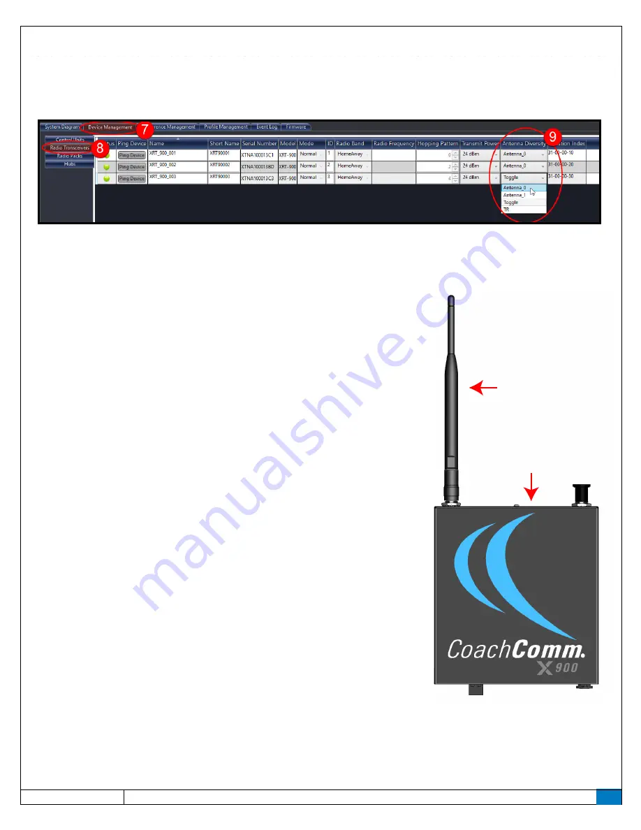
7. Click on the “Device Management” tab of the advanced settings window.
8. Click on the “Radio Transceivers” option in the sub-menu that displays on the Device Management tab. A table of the
system’s RTs will display.
9. Find the Antenna Diversity column, and select
Antenna_0
from the drop-down field for each RT in the table.
10. Continue to the hardware changes in the next section.
Hardware Changes
Make the following changes to your RTs. You only need to make these hardware changes
once.
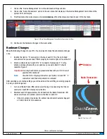
1. Identify the right or “R” connector on the top of each RT. It is the right-hand
connector when you can read “PING” properly from left to right on top of the RT.
2. Attach a whip antenna to each RT’s “R” connector. Remove each “L” whip
antenna and keep them with your system as spare parts. Each RT should
resemble Figure 2.
Important!
Use only CoachComm-approved antennas with your RTs to avoid
possible FCC violations!
Note:
CoachComm is shipping connector caps to place on your RTs’ “L”
connectors once their whip antenna is removed.
After updating your antenna settings you will need to verify everything is working properly
by doing a quick range test:
1. Turn on all Radio Packs (RPs) and ensure they log in by observing that the LQ
numbers on each RP’s display are in the 90s.
2. Walk test each RP approximately 20–30 feet from the Radio Transceiver (RT)
and ensure those LQ numbers remain in the 90s for each RP.
»
If the LQ numbers drop below 90, contact CoachComm Customer Support
at 1.800.749.2761 for assistance.
Figure 1: X-Ware Device Management Tab and Radio Transceivers List View
Antenna
Radio Transceiver
Figure 2:
Front View of RT
Process continues on next page.


