WELDIING GAS ANALYZER
CM-650
5/21/2021
6 |
P a g e
May 21, 2021
U:\Documentation\Projects\CM-650\References\Manual
REV C
3. Log Button: Used to force a data log reading to be saved to the data log file.
4. Power In: Connection port for the power cable.
5. Signal Out: Connection port for the signals sent out. Used to control strobe.
6. 15% Inlet Port: Connection port for the 15% CO2 gas line
7. 25% Inlet Port: Connection port for the 25 % CO2 gas line
Operation
Step 1)
Install the device (Please see instillation page)
Step 2)
Connect Gas lines to appropriate inlet ports:
Ports will be labeled 15% and 25%. The inlets are a standard 1/4 Female NPT. Two
adaptor fittings will be included:
a)
1/4 NPT Male to 5/8-18 Female
b)
1/4 NPT Male barb fitting
Step 3)
Power on the unit:
The device will take roughly 1 minute to begin reading CO2 levels.
Step 4)
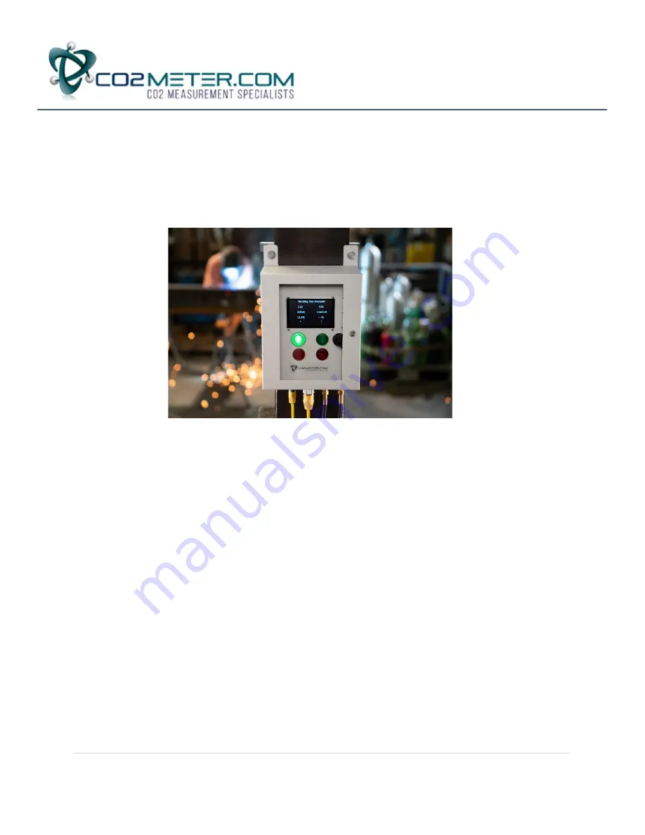
Reading Display and Indicator Lights:
a)
The display will show if the device is in Manual or Automatic mode and will also display the
information for each inlet port. If there is not pressure on the inlet port, it will read inactive.
Once <15 psi is applied to that port it will become active and the device display the
concentration of the gas being sampled.
b) There are RED and GREEN indicator lights for both the 15% and 25% inlet ports. Once
the channels are active, The RED indicator light will be on until the correct connection
range is reached; then the GREEN light will turn on to indicate it is safe to weld


