____________________________________________________________________________
___________________________________________________________________________
User
’s Manual Page 6
6.0 E-STOP TERMINAL
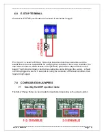
Connect an E-STOP push button as is shown in the below images.
Pin 10 port 1 is used for E-Stop. Since this board controls the enable line, and the
enable line is the one responsible for notifying the controller of the e-stop condition, the
user does not have a direct access to the pin itself, just to the e-stop terminal on the
board. The E-Stop terminal is tied to the enable line and will trigger the e-stop. A fault
or E-Stop triggers a low for 5 seconds to notify the controller of the fault condition, then
resets to high again
7.0 CONFIGURATION JUMPERS
7.1
Selecting the SCHP operation mode
The Safety Charge Pump can be activated or deactivated depending on the jumper position


