background image

AA

13

www.cmtorangetools.com

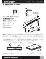
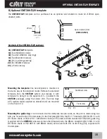
OPTIONAL CMT300-T080 AND CMT300-T127 TEMPLATE

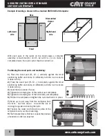
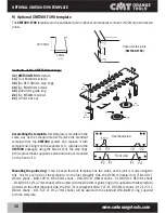
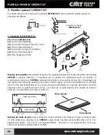
Example of making a drawer with CMT300-T080 and CMT300-T127 template:

X3

X4

Y3

Y2

Y4

Y1

X2

X1

Dismantled 

drawer 

Right-hand 

side

Left-hand 

side

Rear

Front

With each machining run, an assembly is made (X1, X2..., Y1 

Y2), so, to make a complete drawer, eight machining cycles 

have to be carried out.

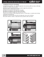
With these two templates, two types of joints can be made, as 

can be seen in the following illustrations.

For the machining, a piece of scrap stock 5mm thicker than the piece to be machines must be placed 

horizontally. This piece of wood used horizontally is only used to support the vertical part to be machined.

Scrap stock

Wood to be 

machined

X1

X2

X4

X3

Y1

Y4

Y2

Y3

Содержание CMT300

Страница 1: ...p 4 ES p 20 FR p 36 IT p 52 DE S 68 PL S 84 RU S 100 CMT300 UNIVERSAL JOINTING SYSTEM Sistema universal de empalme para encajes Système universel pour assemblages à encastrement Sistema di giunzioni universale per incastri Universelle Bohrhilfe für Verbindungen Uniwersalny system do wykonywania połączeń Универсальная соединительная система ...

Страница 2: ......

Страница 3: ... Chiusa di Ginestreto Italia tel_ 39 0721 48571 fax_ 39 0721 481021 e mail_info cmtorangetools com web site_www cmtorangetools com CMT USA inc 7609 Bentley Road Suite D Greensboro NC 27409 USA Phone 336 854 0201 Fax 336 854 0903 e mail_info cmtorangetools com ...

Страница 4: ...ms Whether you are a professional or not our universal assembly system will enable you to make any type of joint easily and rapidly This system can be adapted to any type of router thanks to its special universal sub base in transparent PETG supplied separately 1 Contents of the package When you open the package you will find the following parts inside No Order No Q ty 11 CMT300 01 1 12 CMT300 02 ...

Страница 5: ...other side of the body The components 3 and screws 10 are used to position the wood Tighten the stops 3 on the body 1 using the screws 10 Set the stops in the positions U1 on the top of the system and F1 on the front of the system Fig 3 This diagram enables to mount the template 5 Fit the two adjustable supports 13 on it with the four screws 14 Fig 4 This diagram shows how to install the clamping ...

Страница 6: ...00 To do so just fit the supports 13 between parts 2 and 11 Fig 6 Once the template is positioned it can be adjusted on the two axes X and Y Just tighten or loosen the stop nut 2 for X axis settings and raise or lower the guides 13 for Y axis settings Once the exact setting has been found tighten nut 12 to lock in place Assembly is now complete ASSEMBLING THE CMT300 CMT300 CMT300 Asse X Asse Y Fig...

Страница 7: ...e supplied separately CMT300 SB1 for Ø8 and Ø12mm shanks CMT300 SB2 for Ø6 35 and Ø12 7mm shanks Once the guide is installed on the router a CMT dovetail bit can be fitted for machining the wood 4 Using the CMT300 with a standard CMT300 T128 template The CMT300 system is supplied with a standard template CMT300 T128 with which 12 7mm half blind dovetail joints can be machined using a normal CMT do...

Страница 8: ... not slip 2 Place the wood part Y1 Y2 horizontally against the small positioning buffer and clamp it sufficiently with the bar to ensure it does not slip 3 Level the two pieces of wood 4 Tighten the clamping bar of the vertical part completely 5 Tighten the clamping bar of the horizontal part completely 6 Position the template and tighten the nuts that hold it in place Dismantled drawer Right hand...

Страница 9: ...from the CMT300 system and replace it with the 26 template fixing it on the supports 13 included in the CMT300 package using the screws 14 The stop rings 37 and 38 replace those supplied as standard The 38 rings which have a larger diameter than the 37 ones are mounted on the front in F2 whereas the other 37 rings are mounted on the top part in U1 Fitting the guide ring to use this template it is ...

Страница 10: ...mp it sufficiently with the bar to ensure it does not slip 2 Place the wood part Y1 Y2 horizontally against the small positioning buffer and clamp it sufficiently with the bar to ensure it does not slip 3 Level the two pieces of wood 4 Tighten the clamping bar of the vertical part completely 5 Tighten the clamping bar of the horizontal part completely 6 Position the template and tighten the nuts t...

Страница 11: ...the other template 27 fixing it on the supports 13 included in the CMT300 package using the screws 14 The stop rings 39 and 40 replace those supplied as standard The two rings 39 are mounted on the front in F2 whereas the others 40 are fitted on the front in F1 and are only used for machining a particular structure as can be seen in Fig 7 In this case the upper part of the wood is up against ring ...

Страница 12: ...ng it on the supports 13 included in the CMT300 package using the screws 14 The stop rings 43 and 44 replace those supplied as standard The two longer rings 43 are mounted on the front in F2 whereas the others 44 are fitted on the front in F1 and only used for machining a particular structure as can be seen in Fig 7 In this case the upper part of the wood is up against ring 44 and the lower part u...

Страница 13: ...bly is made X1 X2 Y1 Y2 so to make a complete drawer eight machining cycles have to be carried out With these two templates two types of joints can be made as can be seen in the following illustrations For the machining a piece of scrap stock 5mm thicker than the piece to be machines must be placed horizontally This piece of wood used horizontally is only used to support the vertical part to be ma...

Страница 14: ...l piece 3 Match the ends of the two pieces of wood 4 Tighten the clamping bar of the vertical part completely 5 Tighten the clamping bar of the horizontal part completely 6 Position the template and tighten the nuts to hold it in place 7 Move up to and away from the workpiece from the front not from above to avoid the risk of missing the guide and ruining the joint 8 Position the router and follow...

Страница 15: ...e supports 13 included in the CMT300 package using the screws 14 The stop rings 45 replace those supplied as standard and are mounted on the front in F2 Mounting the guide ring it can be seen that this template has two sides as the joint is made using two bits one for each side of the template On the first straight side the Ø12 7 dovetail bit 818 129 11 with Ø6 35mm shank or 918 129 11 with Ø8mm s...

Страница 16: ...ce it with template 32 fixing it on the supports 13 included in the CMT300 package using the screws 14 The stop rings 46 replace those supplied as standard and are mounted on the front in F2 Mounting the guide ring it can be seen that this template has two sides as the joint is made using two bits one for each side of the template On the first straight side the Ø19mm dovetail bit 718 190 11 Ø6mm s...

Страница 17: ...e first part of the template with the straight slots enables to make the X axis cuts X1 X2 using a CMT dovetail bit and the corresponding guide ring The second dovetail part of the template enables to make the Y axis cuts Y1 Y2 using a CMT straight bit and the corresponding guide ring X3 X4 Y3 Y2 Y4 Y1 X2 X1 Second side of the template to be used with the straight bit First side of the template to...

Страница 18: ...ts 11 Remove the template and leave the scrap stock in place 12 Place the wood part Y1 vertically against the small positioning buffer and clamp the bar sufficiently to ensure it does not slip 13 Match the ends of the two pieces of wood 14 Tighten the clamping bar of the vertical part completely 17 Turn the template on to the second dovetail side Make certain to use the correct guide ring and the ...

Страница 19: ...ructions there is the commercial documentation of the items and relative code numbers of the CMT300 system In particular there are the optional templates the description of the bits use and the relative code numbers We hope you enjoy working with the CMT300 system Fig 1 Fig 2 Fig 3 Fig 4 Fig 6 Fig 5 Fig 7 Fig 6 Fig 8 Fig 6 Wood position Scrap stock Work piece Fig 9 ...

Страница 20: ...mpra de nuestros productos y le deseamos buen trabajo Que sea Ud un profesional o no con nuestro sistema de empalme universal podrá crear fácil y rápidamente cualquier tipo de encaje Este sistema puede adaptarse a cualquier tipo de electrofresadora gracias a la base universal especial de PETG transparente suministrada a parte 1 Contenido del embalaje Al abrir el embalaje encontrará las piezas sigu...

Страница 21: ...a operación en el lado opuesto del cuerpo La piezas 3 y los tornillos 10 sirven para posicionar la pieza de madera Enrosque los topes 3 al cuerpo 1 utilizando los tornillos 10 Coloque los topes en las posiciones U1 en la parte superior del dispositivo y F1 en la parte anterior del mismo Fig 3 Este esquema le permite montar la plantilla 5 Fije sobre el mismo los dos soportes ajustables 13 con los c...

Страница 22: ...ración para la barra anterior Fig 5 Finalmente coloque la plantilla sobre el cuerpo del dispositivo CMT300 Para hacerlo es suficiente introducir los soportes 13 entre las partes 2 y 11 Fig 6 Después de colocada en posición la plantilla puede ajustarla de acuerdo con los dos ejes en X o en Y Es suficiente apretar o aflojar la tuerca de tope 2 para variaciones en X y levantar o bajar las guías 13 pa...

Страница 23: ...anche Ø8 y Ø12mm CMT300 SB2 para enganche Ø6 35 y Ø12 7mm Después de instalada la guía sobre la electrofresadora podrá montar una fresa con cola de milano CMT que realizará la elaboración de su madera 4 Utilización del CMT300 con plantilla estándar CMT300 T128 Junto con el sistema CMT300 se suministra una plantilla estándar CMT300 T128 con la cual podrá realizar empalmes de cola de milano semiocul...

Страница 24: ... deslice 2 Ponga la pieza de madera Y1 Y2 en posición horizontal contra el pequeño paragolpes de posicionamiento y la apriete contra la parte vertical 3 Nivele las dos piezas de madera 4 Apriete de forma definitiva la barra de sujeción de la parte vertical 5 Apriete de forma definitiva la barra de sujeción de la parte horizontal 6 Coloque la plantilla y apriete las tuercas para mantenerla en posic...

Страница 25: ...a plantilla 26 sujetándola sobre los soportes 13 suministrados junto con el CMT300 utilizando los tornillos 14 Los anillos de tope 37 y 38 sustituyen los que vienen con el dispositivo estándar Los anillos 38 que tienen un diámetro superior que los 37 se montan frontalmente en F2 mientras que los 37 tienen que montarse en la parte superior en U1 Montaje de anillo de guía para utilizar esta plantill...

Страница 26: ... de forma suficiente con la barra de modo que no deslice 2 Ponga la pieza de madera Y1 Y2 en posición horizontal contra el pequeño paragolpes de posicionamiento y la apriete contra la parte vertical 3 Nivele las dos piezas de madera 4 Apriete de forma definitiva la barra de sujeción de la parte vertical 5 Apriete de forma definitiva la barra de sujeción de la parte horizontal 6 Coloque la plantill...

Страница 27: ... 13 suministrados junto con el CMT300 utilizando los tornillos 14 Los anillos de tope 39 y 40 sustituyen los que vienen con el dispositivo estándar Los anillos 39 se montan frontalmente en F2 mientras que los 40 se fijan frontalmente en F1 y sirven sólo para la elaboración de una estructura particular como se puede apreciar en la Fig 7 En este caso la parte superior de la madera va a tropezar cont...

Страница 28: ...T300 utilizando los tornillos 14 Los anillos de tope 43 y 44 sustituyen los que vienen con el dispositivo estándar Los anillos 43 más largos se montan frontalmente en F2 mientras que los 44 se fijan frontalmente en F1 y sirven sólo para la elaboración de una pieza de madera con forma particular como se puede apreciar en la Fig 7 En este caso la parte superior de la madera da contra el anillo 44 y ...

Страница 29: ... para hacer un cajón entero será necesario efectuar 8 ciclos de elaboración Con estas dos plantillas es posible realizar dos tipos de encajes como se puede ver en los dibujos siguientes Para la elaboración tiene que posicionar horizontalmente una pieza de maderá que luego se tirará con un grosor de 5mm superior que la pieza que se tiene que trabajar Esta pieza de madera horizontal sirve sólo como ...

Страница 30: ...a vertical 3 Nivele la extremidad de las dos piezas de madera 4 Apriete de forma definitiva la barra de sujeción de la parte vertical 5 Apriete de forma definitiva la barra de sujeción de la parte horizontal 6 Coloque la plantilla y apriete las tuercas para mantenerla en posición 7 Se acerque con su electrofresadora desde adelante y no desde arriba para evitar el riesgo de fallar la guía 8 Una vez...

Страница 31: ...dos junto con el CMT300 utilizando los tornillos 14 Los anillos de tope 45 sustituyen los que vienen con el dispositivo estándar y se montan en posición frontal F2 Montaje del anillo de guía esta plantilla tiene dos lados ya que el encaje se realiza utilizando dos fresas una por cada lado de la plantilla En el primer lado el derecho se utiliza la fresa de cola de milano de Ø12 7 818 129 11 con eng...

Страница 32: ...etándolasobrelossoportes13 suministradosjunto con el CMT300 utilizando los tornillos 14 Los anillos de tope 46 sustituyen los que vienen con el dispositivo estándar y se montan en posición frontal F2 Montaje del anillo de guía esta plantilla tiene dos lados ya que el encaje se realiza utilizando dos fresas una por cada lado de la plantilla En el primer lado el derecho se utiliza la fresa de cola d...

Страница 33: ...era parte de la plantilla con canales derechos permite realizar las X X1 X2 utilizando una fresa de cola de milano CMT y el anillo de guía correspondiente La segunda parte de la plantilla de cola de milano permite realizar las Y Y1 Y2 utilizando una fresa derecha CMT y el anillo de guía correspondiente X3 X4 Y3 Y2 Y4 Y1 X2 X1 Segundo lado de la plantilla que utilizar con la fresa derecha Primer la...

Страница 34: ...realizar todas las X 11 Desmonte la plantilla y deje en su posición la pieza de ayuda 12 Ponga la pieza de madera Y1 en posición vertical contra el pequeño paragolpes de posicionamiento y la apriete de forma suficiente con la barra de modo que no deslice 13 Nivele la extremidad de las dos piezas de madera 14 Apriete de forma definitiva la barra de apriete de la parte vertical 15 Gire la plantilla ...

Страница 35: ... la documentación comercial de los artículos y los códigos correspondientes del dispositivo CMT300 En particular podrá encontrar las plantillas opcionales la descripción de las fresas que utilizar y los códigos correspondientes Le deseamos un empleo provechoso del sistema CMT300 Fig 1 Fig 2 Fig 3 Fig 4 Fig 6 Fig 5 Fig 7 Fig 6 Fig 8 Fig 6 Posición de la pieza de madera Pieza que descartar Pieza que...

Страница 36: ... suivantes SOMMAIRE page 1 Contenu de la confection 36 2 Montage du CMT300 37 3 Installation de la fraiseuse électrique 39 4 Utilisation du CMT300 et du calibre standard CMT300 T128 39 5 Calibre fourni en option CMT300 T064 41 6 Calibre fourni en option CMT300 T080 43 45 46 7 Calibre fourni en option CMT300 T127 44 45 46 8 Calibre fourni en option CMT300 T129 47 49 50 51 9 Calibre fourni en option...

Страница 37: ...pération sur le côté opposé du corps Les pièces 3 et les vis 10 servent au positionnement du bois Visser les butées 3 sur le corps 1 en utilisant les vis 10 Agencer les arrêts aux positions U1 sur la partie supérieure de l installation et F1 sur la partie antérieure de l installation Fig 3 Ce schéma permet de monter le calibre 5 Fixer sur le calibre les deux supports réglables 13 avec les quatre v...

Страница 38: ...corps du CMT300 Pour ce faire il suffit d introduire les supports 13 entre les parties 2 et 11 Fig 6 Une fois que le calibre est en place il est possible de le régler selon deux axes en X ou en Y Il suffit de serrer ou de desserrer l écrou d arrêt 2 pour les variations en X et d élever ou d abaisser les glissières 13 pour les réglages en Y Une fois que la mise au point est effectuée serrer l écrou...

Страница 39: ...rt et en option CMT300 SB1 pour fixation Ø 8 et Ø 12mm CMT300 SB2 pour fixation Ø 6 35 et Ø 12 7mm Une fois que le guide est installé sur la fraiseuse électrique il est possible de monter une fraise en queue d aronde CMT qui effectuera le travail du bois 4 Utilisation du CMT300 et du calibre standard CMT300 T128 Le système CMT300 est fourni avec un calibre standard CMT300 T128 qui permet de réalis...

Страница 40: ...sse pas 2 Mettre la pièce en bois Y1 Y2 à l horizontale contre le petit pare chocs de positionnement et la pousser contre la pièce verticale 3 Mettre les deux pièces à niveau 4 Serrer définitivement la barre de serrage de la pièce verticale 5 Serrer définitivement la barre de serrage de la pièce horizontale 6 Placer le calibre et serrer les écrous pour le maintenir en place Tiroir démonté Bord dro...

Страница 41: ...placer par le calibre 26 en le fixant sur les supports 13 inclus dans le CMT300 au moyen des vis 14 Les anneaux de butée 37 et 38 remplacent ceux de la fourniture standard Les anneaux 38 qui ont un diamètre supérieur à celui des 37 se montent sur le devant dans F2 tandis que les 37 se montent dans la partie supérieure dans U1 Montage de l anneau de guidage Pour utiliser ce calibre il faut démonter...

Страница 42: ... avec la barre de façon à ce qu elle ne glisse pas 2 Mettre la pièce en bois Y1 Y2 à l horizontale contre le petit pare chocs de positionnement et la pousser contre la pièce verticale 3 Mettre les deux pièces à niveau 4 Serrer définitivement la barre de serrage de la pièce verticale 5 Serrer définitivement la barre de serrage de la pièce horizontale 6 Placer le calibre et serrer les écrous pour le...

Страница 43: ... 13 inclus dans le CMT300 au moyen des vis 14 Les anneaux de butée 39 et 40 remplacent ceux de la fourniture standard Les deux anneaux 39 se montent sur le devant dans F2 tandis que les 40 se fixent sur le devant dans F1 et servent uniquement pour le travail d une structure particulière comme le montre la Fig 7 Dans ce cas la partie supérieure du bois bute contre l anneau 40 et la partie inférieur...

Страница 44: ...13 inclus dans le CMT300 au moyen des vis 14 Les anneaux de butée 43 et 44 remplacent ceux de la fourniture standard Les deux anneaux 43 les plus longs se montent sur le devant dans F2 tandis que les 44 se fixent sur le devant dans F1 et servent uniquement pour le travail d une structure particulière comme le montre la Fig 7 Dans ce cas la partie supérieure du bois bute contre l anneau 44 et la pa...

Страница 45: ...r 8 cycles de travail Ces deux calibres permettent de réaliser deux types d encastrements comme il est indiqué sur les figures suivantes Pour le travail placer horizontalement un bois que l on jettera ensuite avec une épaisseur supérieure de 5mm à celles de la pièce que l on envisage de travailler Ce bois horizontal est une pièce qui sert uniquement d appui pour la partie verticale qu sera travail...

Страница 46: ...rticale 3 Mettre à niveau l extrémité des deux pièces 4 Serrer définitivement la barre de serrage de la pièce verticale 5 Serrer définitivement la barre de serrage de la pièce horizontale 6 Placer le calibre et serrer les écrous pour le maintenir en place 7 S approcher de la fraiseuse électrique sur le devant et non pas par le haut pour ne pas courir le risque de rater le guidage 8 Une fois que la...

Страница 47: ...dans le CMT300 au moyen des vis 14 Les anneaux de butée 45 et 38 remplacent ceux de la fourniture standard Montage de l anneau de guidage Il est clair que ce calibre possède deux côtés dans la mesure où l encastrement est effectué en utilisant deux fraises une pour chaque côté du calibre Sur le premier côté le droit on utilisera la fraise à queue d aronde de Ø12 7 818 129 11 à fixation Ø 6 35mm ou...

Страница 48: ...libre 32 en le fixant sur les supports 13 inclus dans le CMT300 au moyen des vis 14 Les anneaux de butée 46 remplacent ceux de la fourniture standard Montage de l anneau de guidage Il est clair que ce calibre possède deux côtés dans la mesure où l encastrement est effectué en utilisant deux fraises une pour chaque côté du calibre Sur le premier côté le droit on utilisera la fraise à queue d aronde...

Страница 49: ...côtés La première partie du calibre avec canaux droits permet réaliser les X X1 X2 en utilisant une fraise à queue d aronde CMT et l anneau de guidage correspondant La deuxième partie du calibre à queue d aronde permet de réaliser les Y Y1 Y2 en utilisant une fraise droite CMT et l anneau de guidage correspondant X3 X4 Y3 Y2 Y4 Y1 X2 X1 Deuxième côté du calibre à utiliser avec la fraise droite Pre...

Страница 50: ...libre et laisser en place la pièce d aide 12 Mettre la pièce en bois Y1 à la verticale contre le petit pare chocs de positionnement et serrer suffisamment avec la barre de façon à ce qu elle ne glisse pas 13 Mettre à niveau l extrémité des deux pièces de bois 14 Serrer définitivement la barre de serrage de la pièce verticale 15 Tourner le calibre sur le deuxième côté à queue d aronde Veiller à uti...

Страница 51: ...utilisation il est possible de trouver la documentation commerciale des articles et les codes relatifs concernant le système CMT300 L on trouvera en particulier les calibres en option la description des fraises à utiliser et les codes correspondants Bon travail avec le système CMT300 Fig 1 Fig 2 Fig 3 Fig 4 Fig 6 Fig 5 Fig 7 Fig 6 Fig 8 Fig 6 Position du bois Pièce écartée Pièce de travail Fig 9 ...

Страница 52: ... suo interno troverete le seguenti parti INDICE pagina 1 Contenuto della confezione 52 2 Montaggio del CMT300 53 3 Installazione dell elettrofresatrice 55 4 Utilizzo del CMT300 e dima standard CMT300 T128 55 5 Dima opzionale CMT300 T064 57 6 Dima opzionale CMT300 T080 59 61 62 7 Dima opzionale CMT300 T127 60 61 62 8 Dima opzionale CMT300 T129 63 65 66 67 9 Dima opzionale CMT300 T190 64 65 66 67 10...

Страница 53: ...ente Ripetete questa operazione nella parte opposta del corpo Le parti 3 e le viti 10 servono al posizionamento del legno Avvitare gli arresti 3 al corpo 1 usando le viti 10 Sistemare gli arresti alle posizioni U1 sulla parte superiore dell impianto e F1 sulla parte anteriore dell impianto Fig 3 Questo schema vi permette di montare la dima 5 Fissare su di esso i due supporti regolabili 13 con le q...

Страница 54: ...iazzerete la dima sul corpo del CMT300 Per far ciò basta introdurre i supporti 13 tra le parti 2 e 11 Fig 6 Una volta posizionata la dima potete regolarla secondo due assi in X o in Y Vi basta stringere o allentare il dado d arresto 2 per variazioni in X e alzare o abbassare le guide 13 per regolazioni in Y Una volta effettuata la messa a punto stringete il dado 12 per il fissaggio L assemblaggio ...

Страница 55: ... separatamente CMT300 SB1 per attacco Ø8 e Ø12mm CMT300 SB2 per attacco Ø6 35 e Ø12 7mm Una volta installata la guida sull elettrofresatrice potrete montare una fresa a coda di rondine CMT che realizzerà la lavorazione del vostro legno 4 Utilizzo del CMT300 con dima standard CMT300 T128 Insieme al sistema CMT300 viene fornita una dima standard CMT300 T128 con cui potrete realizzare unioni a coda d...

Страница 56: ...non scivoli 2 Mettete la parte in legno Y1 Y2 in orizzontale contro il piccolo paracolpi di posizionamento e spingetela contro la parte verticale 3 Livellate i due legni 4 Stringete definitivamente la sbarra di serraggio della parte verticale 5 Stringete definitivamente la sbarra di serraggio della parte orizzontale 6 Piazzate la dima e stringete i dadi per mantenerla in posizione Cassetto smontat...

Страница 57: ... sostituitela con la dima 26 fissandola sui supporti 13 inclusi nel CMT300 tramite le viti 14 Gli anelli di battuta 37 e 38 sostituiscono quelli in dotazione standard Gli anelli 38 che hanno un diametro più grande di quelli 37 si montano frontalmente in F2 mentre quelli 37 vanno montati nella parte superiore in U1 Montaggio dell anello di guida per l utilizzo di questa dima dovrete smontare l anel...

Страница 58: ...sufficientemente con la sbarra in modo che non scivoli 2 Mettete la parte in legno Y1 Y2 in orizzontale contro il piccolo paracolpi di posizionamento e spingetela contro la parte verticale 3 Livellate i due legni 4 Stringete definitivamente la sbarra di serraggio della parte verticale 5 Stringete definitivamente la sbarra di serraggio della parte orizzontale 6 Piazzate la dima e stringete i dadi p...

Страница 59: ...l CMT300 tramite le viti 14 Gli anelli di battuta 39 e 40 sostituiscono quelli in dotazione standard I due anelli 39 si montano frontalmente in F2 mentre quelli 40 si fissano frontalmente in F1 e servono soltanto per la lavorazione di una particolare struttura come potete vedere in Fig 7 In questo caso la parte superiore del legno viene ad inciampare contro l anello 40 e la parte inferiore viene a...

Страница 60: ...CMT300 tramite le viti 14 Gli anelli di battuta 43 e 44 sostituiscono quelli in dotazione standard I due anelli 43 più lunghi si montano frontalmente in F2 mentre quelli 44 si fissano frontalmente in F1 e servono soltanto per la lavorazione di un legno con una particolare forma come si vede in Fig 7 In questo caso la parte superiore del legno viene a sbattere contro l anello 44 e la parte inferior...

Страница 61: ... un cassetto completo vi occorrerà effettuare 8 cicli di lavorazione Con queste due dime avete la possibilità di realizzare due tipi di incastri come potete vedere nei seguenti disegni Per la lavorazione dovete piazzare orizzontalmente un legno che poi butterete via con uno spessore superiore di 5mm a quella della parte che dovete lavorare Questo legno orizzontale è un pezzo che funge solamente da...

Страница 62: ...ale 3 Livellate la fine dei due legni 4 Stringete definitivamente la sbarra di serraggio della parte verticale 5 Stringete definitivamente la sbarra di serraggio della parte orizzontale 6 Piazzate la dima e stringete i dadi per mantenerlo in posizione 7 Avvicinatevi con la vostra elettrofresatrice da davanti e non dall alto per non rischiare di mancare la guida 8 Posizionata l elettrofresatrice se...

Страница 63: ...0 tramite le viti 14 Gli anelli di battuta 45 sostituiscono quelli in dotazione standard e si montano frontalmente in F2 Montaggio dell anello di guida si può vedere che questa dima possiede due lati in quanto l incastro viene eseguito utilizzando due frese una per ogni lato della dima Sul primo lato quello diritto si utilizzerà la fresa a coda di rondine da Ø12 7 818 129 11 con attacco Ø6 35mm o ...

Страница 64: ...2 fissandola sui supporti 13 inclusi nel CMT300 tramite le viti 14 Gli anelli di battuta 46 sostituiscono quelli in dotazione standard e si montano frontalmente in F2 Montaggio dell anello di guida si può vedere che questa dima possiede due lati in quanto l incastro viene eseguito utilizzando due frese una per ogni lato della dima Sul primo lato quello diritto si utilizzerà la fresa a coda di rond...

Страница 65: ...a prima parte della dima con canali diritti permette di realizzare le X X1 X2 utilizzando una fresa a coda di rondine CMT e l anello di guida corrispondente La seconda parte della dima a coda di rondine permette di realizzare le Y Y1 Y2 utilizzando una fresa diritta CMT e l anello di guida corrispondente X3 X4 Y3 Y2 Y4 Y1 X2 X1 Secondo lato della dima da utilizzare con la fresa diritta Primo lato ...

Страница 66: ...1 Smontate la dima e lasciate in posizione il pezzo d aiuto 12 Mettete la parte di legno Y1 in verticale contro il piccolo paracolpi di posizionamento e stringete sufficientemente la sbarra in modo che non scivoli 13 Livellate la fine dei due pezzi di legno 14 Stringete definitivamente la sbarra di serraggio della parte verticale 15 Girate la dima sul secondo lato quello a coda di rondine Attenzio...

Страница 67: ...a d utilizzo potete trovare la documentazione commerciale degli articoli e relativi codici riguardanti il sistema CMT300 Troverete in particolare le dime opzionali la descrizione delle frese da utilizzare e i codici corrispondenti Vi auguriamo un buon utilizzo del sistema CMT300 Fig 1 Fig 2 Fig 3 Fig 4 Fig 6 Fig 5 Fig 7 Fig 6 Fig 8 Fig 6 Posizione legno Pezzo scarto Pezzo lavoro Fig 9 ...

Страница 68: ...e INHALT Seite 1 Packungsinhalt 68 2 Montage der CMT300 69 3 Installation der elektrofräse 71 4 Benutzung der CMT300 und standardschablone CMT300 T128 71 5 Optional Schablone CMT300 T064 73 6 Optional Schablone CMT300 T080 75 77 78 7 Optional Schablone CMT300 T127 76 77 78 8 Optional Schablone CMT300 T129 79 81 82 83 9 Optional Schablone CMT300 T190 80 81 82 83 10 Schlussfolgerungen 83 Nr Bestell ...

Страница 69: ... Sie diesen Vorgang auch auf der anderen Korpusseite Die Teile 3 und die Schrauben 10 dienen zum Positionieren des Holzes Schrauben Sie die Anschläge 3 mit den Schrauben 10 am Korpus 1 an Positionieren Sie die Anschläge auf den Stellen U1 am oberen und F1 am vorderen Teil der Anlage Abb 3 Anhand dieser Skizze können Sie die Schablone 5 montieren Die verstellbaren Auflagen 13 mit den vier Schrauben...

Страница 70: ...m Schluss die Schablone auf dem Korpus der CMT300 Setzen Sie dazu einfach die Auflagen 13 zwischen die Teile 2 und 11 ein Abb 6 Die positionierte Schablone können Sie nun in den Richtungen x und y einstellen Für Einstellungen auf der x Achse einfach die Mutter 2 lockern bzw anziehen für Einstellungen auf der y Achse die Führungen 13 anheben oder absenken Zum Schluss die Mutter 12 wieder anziehen N...

Страница 71: ...0 SB1 für Anschluss Ø8 und Ø12mm CMT300 SB2 für Anschluss Ø6 35 und Ø12 7mm Ist die Führung auf der Fräse installiert können Sie einen CMT Schwalbenschwanzfräser für die Ausführung der Bearbeitung montieren 4 Benutzung der CMT300 mit standardschablone CMT300 T128 Zusammen mit dem System CMT300 wird eine Standardschablone CMT300 T128 geliefert mit der Sie halbverdeckte 12 7 mm Schwalbenschwanzverbi...

Страница 72: ... modo che non scivoli 2 Das Holzteil Y1 Y2 senkrecht gegen den kleinen Anschlag legen und gegen das vertikale Teil drücken 3 Die beiden Holzelemente ausrichten 4 Die Stange zum Feststellen des vertikalen Teils definitiv anziehen 5 Die Stange zum Feststellen des horizontalen Teils definitiv anziehen 6 Die Schablone platzieren und die Stellmuttern anziehen Zerlegte Schublade Rechte Seite Linke Seite...

Страница 73: ...en Sie sie durch die Schablone 26 befestigen Sie die neue Schablone mit den Schrauben 14 an den Auflagen 13 die zum CMT300 gehören Die zur Standardausstattung gehörenden Anschlagringe werden durch die Ringe 37 und 38 ersetzt Die Ringe 38 die einen größeren Durchmesser haben als die Ringe 37 werden vorne an F2 montiert die Ringe 37 im oberen Teil an U1 Montage des Führungsrings Um diese Schablone z...

Страница 74: ...er Stange so einspannen dass es nicht wegrutscht 2 Das Holzteil Y1 Y2 senkrecht gegen den kleinen Ansch lag legen und gegen das vertikale Teil drücken 3 Die beiden Holzelemente ausrichten 4 Die Stange zum Feststellen des vertikalen Teils definitiv anziehen 5 Die Stange zum Feststellen des horizontalen Teils definitiv anziehen 6 Die Schablone platzieren und die Stellmuttern anziehen 7 Immer nur von...

Страница 75: ... 27 befestigen Sie die neue Schablone mit den Schrauben 14 an den Auflagen 13 die zum CMT300 gehören Die zur Standardausstattung gehörenden Anschlagringe werden durch die Ringe 39 und 40 ersetzt Die beiden Ringe 39 vorne in F2 montieren die Ringe 40 vorne in F1 sie werden nur für eine spezielle Struktur benötigt die in Abb 7 gezeigt wird In diesem Fall liegt der obere Teil des Werkstückes am Ring ...

Страница 76: ...efestigen Sie die neue Schablone mit den Schrauben 14 an den Auflagen 13 die zum CMT300 gehören Die zur Standardausstattung gehörenden Anschlagringe werden durch die Ringe 43 und 44 ersetzt Die beiden Längeren Ringe 43 vorne in F2 montieren die Ringe 44 vorne in F1 sie werden nur für Werkstücke mit einer besonderen Form benötigt die in Abb 7 gezeigt wird In diesem Fall liegt der obere Teil des Wer...

Страница 77: ...yklen erforderlich Mit diesen beiden Schablonen können Sie also zweiArten von Verbindungen herstellen wie aus den folgenden Zeichnungen ersichtlich ist Für die Bearbeitung müssen Sie ein Holzstück das 5mm stärker ist als das zu bearbeitende Werkstück und das Sie nachher wegwerfen können waagrecht auflegen Dieses Holzteil fungiert lediglich als Unterlage für das vertikale Werkstück Werkstück Unterl...

Страница 78: ...ten 4 Die Stange zum Feststellen des vertikalen Teils definitiv anziehen 5 Die Stange zum Feststellen des horizontalen Teils definitiv anziehen 6 Die Schablone platzieren und die Stellmuttern anziehen 7 Mit der Elektrofräse immer nur von vorn und niemals von oben zum vom Werkstück gehen da sonst die Gefahr besteht dass Sie die Führung verfehlen und die Verbindung nicht gelingt 8 Die Elektrofräse p...

Страница 79: ...mit den Schrauben 14 an den Auflagen 13 die zum CMT300 gehören Die zur Standardausstattung gehörenden Anschlagringe werden durch die Ringe 45 ersetzt die vorne in F2 montiert werden Montage des Führungsrings Diese Schablone hat zwei Seiten da die Verbindung mit zwei Fräsern je ein Fräser pro Seite ausgeführt wird Auf der ersten geraden Seite benutzt man den Schwalbenschwanzfräser Ø12 7 818 129 11 ...

Страница 80: ...den Schrauben 14 an den Auflagen 13 die zum CMT300 gehören Die zur Standardausstattung gehörenden Anschlagringe werden durch die Ringe 46 ersetzt die vorne in F2 montiert werden Montage des Führungsrings Diese Schablone hat zwei Seiten da die Verbindung mit zwei Fräsern je ein Fräser pro Seite ausgeführt wird Auf der ersten geraden Seite benutzt man den Schwalbenschwanzfräser Ø19mm 718 190 11 Ansc...

Страница 81: ...n Seiten Der ersten Teil der Schablone mit geraden Rillen dient zum Ausführen der X X1 X2 mit einem CMT Schwalbenschwanzfräser und dem entsprechenden Führungsring Der zweite Teil der Schablone Schwalbenschwanz dient zum Ausführen der Y Y1 Y2 mit einem geraden CMT Fräser und dem entsprechenden Führungsring X3 X4 Y3 Y2 Y4 Y1 X2 X1 Zweite Seite der Schablone mit geradem Fräser benutzen Erste Seite de...

Страница 82: ...rholen um alle X Verbindungen auszuführen 11 Nehmen Sie die Schablone ab und lassen Sie die Unterlage liegen 12 Das Holzteil Y1 vertikal gegen den kleinen Anschlag legen und die Stange so weit anziehen dass es nicht verrutschen kann 13 Das Ende der beiden Holzteile ausrichten 14 Die Stange zum Feststellen des vertikalen Teils definitiv festziehen 15 Die Schablone auf die zweite Seite Schwalbenschw...

Страница 83: ...tung finden Sie hier die Unterlagen zu den Komponenten mit den Artikelnummern des Systems CMT300 sowie zu den als Optional erhältlichen Schablonen die Beschreibung der zu benutzenden Fräser und die entsprechenden Artikelnummern Wir wünschen Ihnen eine erfolgreiche Arbeit mit dem System CMT300 Abb 1 Abb 2 Abb 3 Abb 4 Abb 6 Abb 5 Abb 7 Abb 6 Abb 8 Abb 6 Position des Holzes Werkstück Unterlage Abb 9 ...

Страница 84: ...dzinsatysfakcjonującejpracyzichużyciem Bezwzględunato czyjesteśfachowcemczyamatorem naszuniwersalnysystemmontażuumożliwiCiwykonanie każdegorodzajupołączeniałatwoiszybko System ten można dostosować do każdego rodzaju frezarki pionowej z ręcznym posuwem dzięki jego specjalnej uniwersalnejbaziezprzezroczystegotworzywaPETG sprzedawanaoddzielnie 1 Zawartość zestawu Po otwarciu opakowania znajdziesz wew...

Страница 85: ...aciśnij nakrętkę 12 Tę samą procedurę powtórz po drugiej stronie korpusu przyrządu Elementy 3 i śruby 10 służą do ustawiania drewna Zaciśnij ograniczniki 3 na korpusie 1 za pomocą śrub 10 Ustaw ograniczniki w pozycjach U1 na górnej powierzchni przyrządu i F1 na przedniej części przyrządu Ryc 3 Niniejszy rysunek umożliwia montaż szablonu 5 Zamocuj na nim dwa regulowane wsporniki 13 za pomocą cztere...

Страница 86: ...oniec umieść szablon na korpusie przyrządu CMT300 Zamontuj wsporniki 13 pomiędzy elementami 2 i 11 Ryc 6 Poumieszczeniuszablonunamiejscumożnagoregulowaćwdwóchosiach XiY Wystarczytylkodocisnąćlubpoluzować nakrętkę blokującą 2A B aby dokonać ustawień w osi X oraz podnieść lub obniżyć prowadnice 13 aby dokonać ustawień w osiY Po dokonaniu właściwego ustawienia dociśnij nakrętkę 12 aby zablokować szab...

Страница 87: ...elnie CMT300 SB1 dla frezów z trzpieniem Ø8 i Ø12 mm CMT300 SB1 dla frezów z trzpieniem Ø6 35 i Ø12 7 mm Po zainstalowaniu prowadnicy na frezarce można zamontować frez do połączeń na jaskółczy ogon CMT do obróbki drewna 4 Stosowanie CMT300 ze standardowym szablonem CMT300 T128 System CMT300 obejmuje standardowy szablon CMT300 T128 z użyciem którego można dokonywać obróbki 12 7 mm półkrytychpołącze...

Страница 88: ...ednio za pomocą listwy aby nie wypadł 2 Umieśćdrewnianyelement X1 X2 poziomo dosuwającgodoniewielkiego separatora i zaciśnij odpowiednio za pomocą listwy aby nie wypadł 3 Wyrównaj oba kawałki drewna 4 Dociśnij do oporu listwę dociskową części pionowej 5 Dociśnij do oporu listwę dociskową części poziomej 6 Ustaw szablon i dociśnij nakrętki które trzymają go na miejscu Szuflada rozmontowana na częśc...

Страница 89: ... CMT300 i zastąp go szablonem 26 mocując go na wspornikach 13 w zestawie CMT300 za pomocą śrub 14 Pierścienie blokujące 37 i 38 zastępują pierścienie standardowe z zestawu Pierścienie 38 które mają większą średnicę niż pierścienie 37 montuje się z przodu w pozycji F2 natomiast pierścienie 37 montuje się na części górnej w pozycji U1 Montaż pierścienia prowadzącego aby móc korzystać z tego szablonu...

Страница 90: ...ratora i zaciśnij odpowiednio za pomocą listwy aby nie wypadł 2 Umieść drewniany element X1 X2 poziomo dosuwając go do niewielkiego separatora i zaciśnij odpowiednio za pomocą listwy aby nie wypadł 3 Wyrównaj oba kawałki drewna 4 Dociśnij do oporu listwę dociskową części pionowej 5 Dociśnij do oporu listwę dociskową części poziomej 6 Ustaw szablon i dociśnij nakrętki aby przytrzymać go na miejscu ...

Страница 91: ...cując go na wspornikach 13 w zestawie CMT300 za pomocą śrub 14 Pierścienie blokujące 39 i 40 zastępują pierścienie standardowe z zestawu Dwa pierścienie 39 montuje się z przodu w pozycji F2 natomiast pozostałe 40 montuje się z przodu w pozycji F1 i stosuje tylko do obróbki konkretnych konstrukcji jak pokazano na Ryc 7 W takim przypadku górna część elementu drewnianego będzie się opierać o pierście...

Страница 92: ... w zestawie CMT300 za pomocą śrub 14 Pierścienie blokujące 43 i 44 zastępują pierścienie standardowe z zestawu Dwa dłuższe pierścienie 43 montuje się z przodu w pozycji F2 natomiast pozostałe 44 montuje się z przodu w pozycji F1 i stosuje tylko do obróbki konkretnych konstrukcji jak pokazano na Ryc 7 W takim przypadku górna część elementu drewnianego będzie się opierać o pierścień 44 a dolna część...

Страница 93: ...obrabianejestjedno połączenie X1 X2 Y1 Y2 zatem aby wykonać całą szufladę należy przeprowadzić osiem cykli pracy Za pomocą tych dwóch szablonów można wykonywać dwa rodzaje połączeń jak pokazano na ilustracjach Do obróbki należy poziomo ustawić pomocniczy element grubszy od obrabianego przedmiotu o 5 mm Taki kawałek drewna ustawiony poziomo służy wyłącznie do podparcia elementu który będzie obrabia...

Страница 94: ...nowego 3 Połącz końce dwóch kawałków drewna ze sobą 4 Dociśnij do oporu listwę dociskową części pionowej 5 Dociśnij do oporu listwę dociskową części poziomej 6 Ustaw szablon i dociśnij nakrętki aby przytrzymać go na miejscu 7 Ruchy do i od obrabianego przedmiotu wykonuj od przodu nie od góry aby uniknąć ryzyka pominięcia prowadnicy i zniszczenia połączenia 8 Ustaw frezarkę i poruszaj się zgodnie z...

Страница 95: ...erścienie blokujące 45 zastępują pierścienie standardowe znajdujące się w zestawie i montuje się je z przodu w pozycji F2 Montażpierścieniaprowadzącego jakwidać szablontenmadwiestrony gdyżpołączeniejestwykonywanezapomocądwóch frezów po jednym dla każdej ze stron szablonu Po pierwszej prostej stronie należy zastosować frez do połączeń na jaskółczy ogon Ø12 7 818 129 11 z trzpieniem Ø6 35 mm lub 918...

Страница 96: ...300 za pomocą śrub 14 Pierścienie blokujące 46 zastępują pierścienie standardowe znajdujące się w zestawie i montuje się je z przodu w pozycji F2 Montażpierścieniaprowadzącego jakwidać szablontenmadwiestrony gdyżpołączeniejestwykonywanezapomocądwóch frezów po jednym dla każdej ze stron szablonu Po pierwszej prostej stronie należy zastosować frez do połączeń na jaskółczy ogon Ø19 mm 718 190 11 z tr...

Страница 97: ...a część szablonu z prostymi rowkami umożliwia wykonywanie cięć w osi X X1 X2 za pomocą frezu do połączeń na jaskółczy ogon CMT i odpowiedniego pierścienia prowadzącego Druga część na jaskółczy ogon szablonu umożliwia wykonywanie cięć w osi Y Y1 Y2 za pomocą frezu prostego CMT i odpowiedniego pierścienia prowadzącego X3 X4 Y3 Y2 Y4 Y1 X2 X1 Druga strona szablonu do pracy z frezem prostym Pierwsza s...

Страница 98: ...ać wszystkie cięcia w osi X 11 Wyjmij szablon i pozostaw pomocniczy kawałek drewna na miejscu 12 Umieśćdrewnianyelement Y1 pionowo dosuwającgodoniewielkiegoseparatoraizaciśnijodpowiedniozapomocąlistwy aby nie wypadł 13 Połącz końce dwóch kawałków drewna ze sobą 14 Dociśnij do oporu listwę dociskową części pionowej 17 Obróć szablon na drugą stronę na jaskółczy ogon Pamiętaj aby zastosować właściwy ...

Страница 99: ...mentacja handlowa dla poszczególnych elementów i odpowiadające im numery katalogowe systemu CMT300 Dostępne są opcjonalne szablony opisy stosowanych frezów i odpowiadające im numery katalogowe Mamy nadzieję że praca z systemem CMT300 przyniesie Ci dużo satysfakcji Ryc 1 Ryc 2 Ryc 3 Ryc 4 Ryc 6 Ryc 5 Ryc 7 Ryc 6 Ryc 8 Ryc 6 Pozycja drewna Element pomocniczy Obrabiany przedmiot Ryc 9 ...

Страница 100: ...с за приобретение нашей продукции и желаем многих часов приятной работы Настоящее универсальное шипорезное приспособление позволит Вам быстро и легко изготавливать соединения любых типов Шипорезное приспособление может использоваться с любым фрезером благодаря универсальной подошве приобретается отдельно 1 Комплектация набора Артикул к во 100 101 102 103 104 106 107 109 110 111 1 10 11 12 13 14 15...

Страница 101: ...пусу 1 Прикрепите две втулки 3 в позицию U1 на верхней стороне корпуса и две в позицию F1 на передней стороне Рисунок 3 Установка шаблона 5 Прикрутите к шаблону два регулируемых держателя 13 с помощью винтов 14 Рисунок 4 На рисунке показывается как монтировать прижимные планки фиксирующие заготовки в нужной позиции Покрытие поверхности планок позволяет надежнее удерживать заготовки во время обрабо...

Страница 102: ...включается копировальная втулка с расстоянием 50 мм между центрами крепежных отверстий Центрирующий штифт Копировальная втулка Фрезер Если у Вашего фрезера соответствующие отверстия располагаются на ином расстоянии Вы можете приобрести универсальную подошву для крепления копировальных втулок Диаметр указанной подошвы 170 мм к ней прилагается центрирующий штифт Универсальная подошва для закрепления...

Страница 103: ...оковина Передняя стенка При каждой операции сразу обрабатывается одно угловое соединение по две детали X1 и Y1 X2 и Y2 Таким образом для изготовления ящика требуется четыре цикла Закрепление заготовок и фрезерование 1 Поместите заготовку X1 X2 вертикально вплотную к ограничителю и слегка зафиксируйте прижимной планкой 2 Поместите заготовку Y1 Y2 горизонтально вплотную к ограничителю и слегка зафик...

Страница 104: ...тыре цикла Задняя стенка Ящик в разобранном виде Левая боковина Правая боковина Передняя стенка При каждой операции сра 5 Использование шаблона CMT300 T064 Шаблон CMT300 T064 приобретается отдельно и предназначен для изготовления глухих мини соединений ласточкин хвост в полдерева 11 3 мм 6 мм Миниатюрные соединения ласточкин хвост в полдерева 6 35 мм Комплектация шаблона CMT300 T064 10 Четыре винт...

Страница 105: ... притяните прижимной планкой 3 Выравняйте обе заготовки 4 Полностью затяните вертикальную прижимную планку 5 Полностью затяните горизонтальную прижимную планку 6 Установите шаблон и закрепите его 7 Двигайте фрезер в горизонтальной плоскости ни в коем случае не сверху во избежание повреждений соединения 8 Отфрезеруйте соединение двигая копиро вальную втулку по шаблону 9 Первая пара деталей готова п...

Страница 106: ... же как и стандартный Замените стандартный шаблон шаблоном 27 Закрепите упоры 13 винтами 14 обе позиции входят в комплектацию шипорезного приспособления CMT300 Ограничительные втулки 39 и 40 заменяют стандартные ограничители Два ограничителя 39 монтируются спереди в позиции F2 в то время как ограничители 40 устанавливаются спереди в позиции F1 и используются для фрезерования специфического вариант...

Страница 107: ...одят в комплект шипорезного приспособления CMT300 Ограничители 43 и 44 устанавливаются вместо стандартных ограничительных втулок Два длинных ограничителя 43 монтируются с передней стороны в позиции F2 в то время как другие ограничители 44 располагаются спереди в позиции F1 и используются только для фрезерования специфического варианта как на рисунке 7 В этом случае верхняя заготовка выравнивается ...

Страница 108: ...е вертикальную прижимную планку 5 Полностью затяните горизонтальную прижимную планку 6 Установите и закрепите шаблон 7 Двигайте фрезер только в горизонтальной плоскости ни в коем случае не сверху во избежание повреждения соединения 8 Закончите фрезерование 9 Одна поверхность обработана повторите операции необходимое количество раз Пример изготовления ящика с помощью шаблонов CMT300 T080 и CMT300 T...

Страница 109: ...его шаблоном T129 31 Прикрепите упоры 13 из комплекта шипорезного приспособления CMT300 с помощью винтов 14 входят в комплект шипорезного приспособления CMT300 Ограничители 45 заменяют стандартные и крепятся спереди в позиции F2 19 из комплекта СМТ300 Установка копировальной втулки Шаблон двухсторонний так что соединение изготавливается с помощью двух фрез каждая для своей стороны шаблона На сторо...

Страница 110: ...входят в комплект шипорезного приспособления CMT300 Ограничительные втулки 46 заменяют стандартные и устанавливаются спереди в позиции F2 из компл СМТ300 Из комплекта СМТ300 Вид сверху Вид спереди Установка копировальной втулки шаблон CMT300 T190 двухсторонний так как соединение изготавливается с применением двух фрез каждая для своей стороны шаблона С одной стороны прямоугольные выступы используе...

Страница 111: ...пировальной втулки Вторая сторона шаблона используется с прямой пазовой фрезой Первая сторона шаблона используется с фрезой ласточкин хвост При фрезеровании деталей горизонтально закрепляется вспомогательная накладка толщина которой на 5 мм больше толщины заготовок она жестко фиксирует край заготовки Обрабатываемая деталь Вспомогательная накладка Закрепление деталей и фрезерование 1 Закрепите стор...

Страница 112: ...тору CMT Utensili S p A ООО ЦРИ 117449 Москва ул Карьер 2А стр 1 495 229 49 72 www woodwork ru woodwork ru gmail com 10 Первая сторона готова повторите операцию для всех сторон по оси X X1 X2 11 Уберите шаблон вспомогательную накладку оставьте на месте 12 Поместите вертикально в шипорезное приспособление сторону Y1 и слегка закрепите прижимной планкой 13 Совместите края обеих деревянных деталей 14...

Страница 113: ...113 NOTE www cmtorangetools com ...

Страница 114: ...114 NOTE www cmtorangetools com Note ...

Страница 115: ...115 NOTE www cmtorangetools com ...

Страница 116: ...archio riportato in questo sito e nei cataloghi dei prodotti CMT rimane di proprietà dei rispettivi produttori CMT die CMT Logos CMT ORANGE TOOLS und die orangene Farbe der Werkzeugflächen sind eingetragene Warenzeichen von C M T Utensili S p A Dieses Dokument wurde Ihnen nur zur privaten Nutzung zugesendet Jede Art von Nutzung und oder Vervielfältigung ist ohne die schriftliche Genehmigung von CM...

Отзывы: