background image

PM4/8/12/16 & PM4/8-SA Installation and User Guide v1.1

1

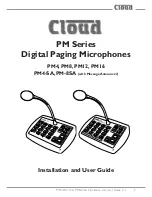
PM Series 

Digital Paging Microphones

PM4, PM8, PM12, PM16

PM4-SA, PM-8SA 

(with Message Announcer)

Installation and User Guide

Содержание PM-8SA

Страница 1: ...PM4 8 12 16 PM4 8 SA Installation and User Guide v1 1 1 PM Series Digital Paging Microphones PM4 PM8 PM12 PM16 PM4 SA PM 8SA with Message Announcer Installation and User Guide...

Страница 2: ...PM4 8 12 16 PM4 8 SA Installation and User Guide v1 1 2...

Страница 3: ...PM4 8 12 16 PM4 8 SA Installation and User Guide v1 1 3 PM4 8 12 16 PM4 SA PM 8SA Digital Paging Microphones...

Страница 4: ...ore zones 14 Paging all zones 15 Paging a Zone Group 15 Announcement Interruption Multiple PM systems only 15 Using the PM SA models User Instructions 16 General Dos and Don ts 16 Paging one or more z...

Страница 5: ...1 26 Cables and Connections 27 Connecting the PM to a mixer via the digital interface 27 Connecting the PM to a mixer via the analogue interface 28 Connecting a PM SA for external message triggering...

Страница 6: ...ring of the host device and or the building is faulty the microphone could present a shock hazard Fitting a suitable earth leakage circuit breaker e g 30 mA RCD type to the mains supply of the host de...

Страница 7: ...ing basic features Individual and multiple zone selection for both paging and messages messages apply to SA models only External NC NO message triggering SA models only Definable zone groups with grou...

Страница 8: ...d to be considered when multiple PMs are interconnected on a network The manual covers both standard PM microphones and the SA models which include a digital sound store for pre recorded messages The...

Страница 9: ...re loaded with Sample chime MP3 files Readme text document about recording messages and chimes PDF version of this manual Installed inside microphone If any items are received in a damaged state or ar...

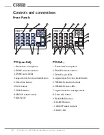
Страница 10: ...phone 2 ZONE selection buttons 3 ZONE select LEDs 4 Legend areas for zone identification 5 CALL ALL button 6 TALK button 7 CLEAR button 8 GROUP select buttons 9 BUSY LED PM SA 1 Gooseneck microphone 2...

Страница 11: ...rophone functions to the PM4 and PM8 but also include Spot Announcer capability Up to four PM4 SA or eight PM8 SA pre recorded messages can be stored internally on a standard SD memory card As well as...

Страница 12: ...ey Not to scale SD card Insert the card oriented as shown pins away from you and slide into the card holder as far as it will go Sound files types The PM SA is able to play sound files recorded in eit...

Страница 13: ...s used as the pre announcement page chime Pre recorded messages may be preceded by either C_1 mp3 or C_2 mp3 or their wma equivalents Additionally any chime file may be assigned to a zone group to pre...

Страница 14: ...Don t release the TALK button until the announcement is finished Don t twist the gooseneck into odd shapes it isn t a toy Paging one or more zones 1 Press the ZONE button s for the zone s to which the...

Страница 15: ...lter the group definition 5 Release the TALK button Announcement Interruption Multiple PM systems only If the system has more than one PM microphone it is possible that announcements may be attempted...

Страница 16: ...s finished Don t twist the gooseneck into odd shapes it isn t a toy Familiarise yourself with the contents of the pre recorded messages sending the wrong one can be embarrassing Paging one or more zon...

Страница 17: ...se the TALK SEND button The BUSY LED will illuminate for the duration of the message 4 Zones may be selected deselected during the message NOTE Once the message is finished the zone and message select...

Страница 18: ...sponding to the zones defined for the group will illuminate 2 Press and hold down the TALK SEND button 3 Make the announcement 4 Zones may be added removed during the announcement NOTE this is only pe...

Страница 19: ...ill cancel the operation Announcement Interruption Multiple PM systems only If the system has more than one PM microphone it is possible that announcements or message broadcasts may be attempted from...

Страница 20: ...panel components are mounted is connected to the lower PCB by a ribbon cable Take care not to stretch or snag either this or the cable from the gooseneck mic The ribbon cable may be unplugged from the...

Страница 21: ...ength of screw protruding and try again Repeat until a good tight fit is obtained Refer to the illustration below for drilling instructions Fitting the MI100166 gooseneck microphone The standard goose...

Страница 22: ...supply can be connected to the PM via the 2 1 mm coaxial power socket on the rear panel A suitable external PSU is the Cloud CPM PSU one is supplied with each SA model but may otherwise be obtained fr...

Страница 23: ...ith the Digital Paging Interface can obtain power through this connection In systems with multiple daisy chained PMs it is only the last PM on the network i e that connected directly to the host which...

Страница 24: ...ilable from various Cloud host mixers etc for powering additional items Host Available Current DCM 1 650 mA Z4II 120 mA Z8II 190 mA CX163 Use ext PSU CX263 Use ext PSU 36 50 Use ext PSU 46 50 80 mA Th...

Страница 25: ...50 mA Bose EQ Modules BEQ M8 M32 MA12 402 502A 802 MB4 MB24 502B 502BEX 12 mA BEQ LT3202 LT4402 LT9402 LT9702 17 mA BEQ M16 DS100 DS16 M1B 34 mA Amina EQ Modules EQ AIWX 9 mA EQ LFIT 12 mA Soundtube E...

Страница 26: ...be supplied with DC power by a Cloud DCM 1 1 Via the Digital Paging Interface The CAN PORT OUT connector on the PM SA is wired for power so a PM connected via this can obtain power through the interf...

Страница 27: ...is transmitted from the OUT connector to the IN connector on the next microphone or mixer in the chain To connect the PM to a Cloud host mixer via the Digital Paging Interface connect the OUT port of...

Страница 28: ...e required Connecting the PM to a mixer via the analogue interface In addition to the Digital Paging Interface the PM incorporates an analogue interface permitting the PM to be used with any Cloud or...

Страница 29: ...Zone 10 Select TERM4 Z10 Zone 2 Select TERM2 Z2 Zone 11 Select TERM4 Z11 Zone 3 Select TERM2 Z3 Zone 12 Select TERM4 Z12 Zone 4 Select TERM2 Z4 Zone 13 Select TERM4 Z13 Zone 5 Select TERM2 Z5 Zone 14...

Страница 30: ...6 50 host mixer which has a typical 4 zone short to ground access port TERM 8 TERM 2 TERM 1 HOT COLD GND Z 1 Z 2 Z 3 Z 4 0 V V M IC 1 IN PAG ING ACCESS HOT COLD GND Z 1 Z 2 Z 3 Z 4 0 V V PM 4 PAG ING...

Страница 31: ...commanded by the PM s own front panel buttons these continue to operate as normal The message trigger control cable may be a screened or unscreened multicore cable with a number of cores suitable for...

Страница 32: ...is is because connecting the PM SA s common 0V to items of equipment running on widely separated AC mains outlets can frequently be problematic The trigger inputs are diode clamped and may be connecte...

Страница 33: ...efinitions so that they cannot be inadvertently altered by users See Lock Groups on page 37 for details of this option NOTE if any zone access is to be restricted by using the PM s Zone Disabling feat...

Страница 34: ...ibility in chime assignment When a message is assigned to a zone group as described above the chime file with the same number as the selected message file is assigned as well Thus if message button 3...

Страница 35: ...need to be disconnected and then reconnected When removing jumpers it is recommended that the link remains connected to one leg of the header to prevent losing it Mic Level Mic volume may be adjusted...

Страница 36: ...the analogue interface If the analogue interface is being used to connect the PM to the host mixer the access cable connections see 2 Zone Selection Control Cable on page 29 should be altered to matc...

Страница 37: ...ill automatically cancel selected zones and any selected message SA models only when the TALK TALK SEND or CALL ALL buttons are released NOTE With auto reset enabled if a zone selection and message se...

Страница 38: ...as been commanded by a HIGH priority PM a message or paging announcement from a PM set to NORMAL priority will not be broadcast similarly a message commanded from a NORMAL priority PM will be interrup...

Страница 39: ...with the PM SA four of these C_1 mp3 to C_4 mp3 are recordings of the analogue chimes available from the standard non SA PM Files C_5 mp3 to C_8 mp3 are respectively duplicates of these Page Chime Th...

Страница 40: ...mes max in PM SA4 Power On Non Volatile Memory NVM Reset An internal non volatile memory NVM stores user settings such as Group definitions and Zone enabling so that these are restored automatically i...

Страница 41: ...ophone is now in Disable Group Edit mode 5 Continue to hold the CLEAR button and complete the selection de selection process with the ZONE buttons 6 Release the CLEAR button once the selection is comp...

Страница 42: ...erminations set ON intermediate PMs should have their terminations set to OFF CDPM GAIN dB IN THRU 10 10 IN OUT OUT M ix er M ix er OUT OUT Term ination ON Term ination ON Term ination OF F CDPM IN TH...

Страница 43: ...m p er with one p osition i e p resent or not DCM 1 Jumper Locations For details of how to set the host mixer s Digital Paging Interface termination correctly in other models please refer to the docum...

Страница 44: ...lluminate while paging or messaging on SA models is taking place regardless of which microphone is being used System Interconnection Multiple PMs should be interconnected in daisy chain fashion via th...

Страница 45: ...Cables and Connections on page 27 The Digital Paging Interface also permits PMs to be intermixed with the older Cloud CDPM paging microphones on the same network Refer to the separate CDPM Installatio...

Страница 46: ...n ON This requires no alteration in single PM systems but in multiple PM systems only the microphone at the far end of the network may have its termination ON all others must have their terminations s...

Страница 47: ...n progress As any one microphone will probably be located in earshot of only one zone s loudspeakers it is possible for a user to page or broadcast a message to a zone and operators at other microphon...

Страница 48: ...Only one PM in a network will require the analogue interface for the whole network to be connected to a short to ground paging system This should be the PM nearest to the host mixer as with a system...

Страница 49: ...nk is left connected to one leg of the header to prevent loss of the link When making internal adjustments please ensure that you Disconnect power to the unit before accessing the PCB If the microphon...

Страница 50: ...lt J1 Chime Select 1 ON J2 Chime Select 2 OFF J3 Chime Select 4 OFF J4 Digital Paging Interface termination ON J5 Chime On Off ON J6 Internal Chime On Off ON J7 NVM Reset OFF J8 High Priority OFF J9 L...

Страница 51: ...nation ON J6 Internal Chime On Off ON J7 NVM Reset OFF J8 High Priority OFF J9 Lock Groups OFF J10 Auto reset zone selection ON J11 Zone Offset 8 OFF J12 Zone Offset 4 OFF J13 Zone Offset 2 OFF J14 Zo...

Страница 52: ...Paging Interface RJ45 Analogue Zone Access Output Short to Ground Audio Output Messages Number of messages 4 or 8 internal speaker Card format SD SDHC MiniSD SDHC MicroSD SDHC Max card size 2 GB SD 3...

Страница 53: ...PM4 8 12 16 PM4 8 SA Installation and User Guide v1 1 53...

Страница 54: ...PM4 8 12 16 PM4 8 SA Installation and User Guide v1 1 54...

Страница 55: ...PM4 8 12 16 PM4 8 SA Installation and User Guide v1 1 55...

Страница 56: ...www cloud co uk www cloudusa pro...

Отзывы: