CLIVET WSH-EE 101 Скачать руководство пользователя страница 9


M03Q40G6-03 30/07/08 

pag 

RESIDUAL RISKS 


GENERAL 

This section lists some of the more common situations 
which, being beyond the control of the manufacturer, could 
be a source of risk to persons or property. 
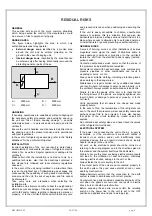
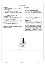
DANGER AREA 

The figure below highlights the area in which only 
authorised personnel may operate. 

• 

External danger zone

, identified by a precise area 

around the unit and its vertical projection on the 
ground in the case of hanging unit. 

• 

Internal danger zone

, identified by the area that can 

be entered only after having intentionally removed the 
protecting panels or parts of these. 

A

B

C

D


A =   

2000mm 

B =   

2000mm 

C =  

2000mm 

D =  

2000mm 


HANDLING 

If handling operations are undertaken without adopting all 
the necessary safety procedures and exercising due care, 
the unit can fall or topple, causing damage — possibly 
extremely serious — to persons and/or property, and to the 
unit itself.  
Ensure the unit is handled and manoeuvred as directed on 
the packing and in the present manual, and in accordance 
with local regulations. 
In the event of refrigerant gas escaping, refer to the “Safety 
datasheet” for the particular refrigerant. 
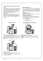
INSTALLATION 

Incorrect installation of the unit can result in water leaks, 
accumulation of condensate, escape of refrigerant, electric 
shocks, fire, as well as irregular operation or damage to the 
unit itself.  
Make certain that the installation is carried out only by a 
qualified technician, also that the directions contained in 
this manual are followed and local statutory regulations 
observed.  
In the event of the unit being installed in a site where there 
is even the slightest risk of inflammable gas escapes and 
consequently the possibility of such gases accumulating in 
area around the unit, the risk of explosion and fire cannot 
be discounted.  
Take every care and precaution when selecting the 
installation site.  
Installation on a structure not able to bear the weight and/or 
afford a secure anchorage of the equipment may cause the 
unit to fall and/or topple, resulting in damage to persons or 
property, or to the unit itself. Make certain that every care 

and precaution is taken when positioning and securing the 
unit. 
If the unit is easily accessible to children, unauthorized 
persons or animals, this is a situation that can give rise 
accidents and injuries, perhaps serious. Install the unit in a 
place where access is allowed only to authorized persons, 
or install barriers or guards preventing unauthorized entry. 

GENERAL RISKS 

A smell of burning, smoke or other indications of serious 
irregularity could signal the onset of situations liable to 
cause damage to persons or property or to the unit itself. 
Isolate the unit from the electrical power supply (red-and-
yellow) switch.  
Contact an authorized service centre so that the source of 
the problem can be identified and remedied. 
Accidental contact with heat exchange coils, compressors, 
pressure pipelines or other components can result in 
wounding or burns, or both.  
Always wear suitable clothing, including protective gloves, 
when working in the danger area. 
Maintenance or repairs carried out by unskilled operatives 
can result in harm or damage to persons and property, or to 
the unit itself. Always contact an authorized service centre. 
Failure to close the panels of the unit, or to check that all 
the fixing screws of the panels are properly tightened, can 
result in harm or damage to persons or property, or to the 
unit itself.  
Verify periodically that all panels are closed and made 
properly secure. 
In the event of fire, the temperature of the refrigerant can 
rise to the point that pressure will exceed safety levels and 
perhaps cause fluid to be projected. It may also happen 
that parts of the circuit isolated by closed valves will 
explode.  
Do not stand near safety valves, and never leave the valves 
of the refrigerant circuit closed. 
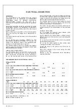
ELECTRICAL SYSTEM 

If the power line connecting the unit to the a.c. supply is 
incomplete, or if the connection is made with cables of 
incorrect cross section and/or with insufficiently rated 
protective devices, this can result in electric shock, toxicity 
hazard, damage to the unit or fire.  
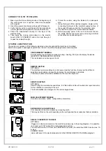
All work on the electrical system should be carried out 
referring to the wiring diagram and to the directions given in 
this manual, and the system itself must be dedicated. 
Failure to secure the cover enclosing electrical components 
can lead to the infiltration of dust and water, ultimately 
causing electric shocks, damage to the unit, or fire.  
Always fasten the cover securely to the unit. 
If live metal parts of the unit are not connected properly to 
the earth system, they can cause electric shock or even 
death by electrocution.  
Make absolutely certain that the connection to the earth 
system is made in accordance with correct practice. 
Contact with live parts rendered accessible internally of the 
unit when the guards are removed can result in electric 
shock, burns or death by electrocution.  
Before exposing these parts, make certain the isolating 
switch on the power line to the unit is set to the OFF 
position and padlocked, and post a warning sign. 

Содержание WSH-EE 101

Страница 1: ...WSH EE WSHH EE 17 21 31 41 51 61 71 81 91 101 121 WATER COOLED WATER CHILLER FOR INDOOR INSTALLATION Installation and Use Manual M03Q40G6 03 21 11 07...

Страница 2: ......

Страница 3: ...8 CONNECTION TO THE MAINS 19 SYSTEM COMPOSITION 19 FUNCTIONAL CONNECTIONS 20 S T A R T U P 2 8 PRELIMINARY CHECKS 28 REFRIGERANT SYSTEM 28 WATER SYSTEM 28 ELECTRICAL SYSTEM 28 VERIFy tensions absorpti...

Страница 4: ...AL NUMBER This provides unique identification of the machine It makes it possible to trace the specific features of the unit and to identify the components installed in it Without this number it is no...

Страница 5: ...ases 8 in the utility side exchanger the refrigerant evaporates and absorbs heat from the water that returns from the equipment underfloor piping fan coil cooling it 9 the refrigerant at gaseous statu...

Страница 6: ...ining the system at a safety temperature in WINTER MAINTENANCE function Put the unit in OFF parameter 45 must be 1 yellow led is flashing Minimize the consumptions maintaining the system at a safety t...

Страница 7: ...dify the water temp in MAINTENANCE heating Control parameter parametro 43 Modify the water temp in MAINTENANCE cooling Control parameter 42 Only by SERVICE keypad A L A R M S T A T U S S E T only WSHH...

Страница 8: ...ct the instructions given in this manual will cause the warranty to lapse INTENDED USE The unit must only be used for the specific purpose it was designed L unit destinata al raffreddamento riscaldame...

Страница 9: ...zed entry GENERAL RISKS A smell of burning smoke or other indications of serious irregularity could signal the onset of situations liable to cause damage to persons or property or to the unit itself I...

Страница 10: ...er Chart No FRIG 8 Product R 410A Identification of the supplier See heading or bottom of page No of emergency telephone See heading or bottom of page 02 Composition information on ingredients Substan...

Страница 11: ...ed from the driver compartment Verify that the driver is informed on the potential risk of the load and that he knows what to do in case of an accident or emergency Before starting the transport verif...

Страница 12: ...ressure of the circuits can assume values which activate the safety valves HANDLING The operation of handling the unit must be carried out respecting the instructions of the safety norms in force Legi...

Страница 13: ...accessible only to qualified and authorized personnel 2 SAFETY VALVE only if present on the unit the installer is responsible for evaluating the opportunity of installing drain tubes in conformity wi...

Страница 14: ...tect the tubes with heating cables under the tubes insulation empty the system by verifying that o no taps are closed so they can not trap the water even after emptying o there are no low points where...

Страница 15: ...essure switch 13 Discharge cock 14 inertial storage tank The accumulation tank is necessary in the event of the following the water in the system is very low the unit will not be used in a private hou...

Страница 16: ...s also required when geothermal probes are used WASHING THE SYSTEM Carefully wash the system by using clean water and discharge it before connecting the unit CONTROL OF FLOW RATE This makes it possibl...

Страница 17: ...n double temperature underfloor heating manages the elements of a mixed system with underfloor piping fan coil radiators circulator mixer valve outlet probe see details in the ELECTRICAL CONNECTIONS s...

Страница 18: ...ose value should be determined according to the plant features The section of supply cables and protection cable must be seized according to the characteristics of the protections used SIGNALS DATA LI...

Страница 19: ...TERMINAL Permits setting the unit function modes cooling heating ECO and to display the alarms ELECTRIC REFRIGERATOR WATER This is standard on certain types of unit L N 91 92 STA TUS SET ALA RM 2 1 RE...

Страница 20: ...he bridge should not be removed 2 CHANGING FROM SUMMER TO WINTER USING THE REMOTE CONTROL This function is activated with the 163 remmode 1 parameter Selection switch open unit in heating mode selecti...

Страница 21: ...p 1 0 IN REPLACEMENT OF THE COMPRESSOR the heaters operate only when the compressor is disabled due to an external temp lower than par 180 1 1 MAIN ADJUSTMENT UNIT IN HEATING MODE in heat pump mode th...

Страница 22: ...oiler in case of unit shutdown MAINTENANCE With the unit coupled to a boiler the maintenance function if enabled activates the boiler instead of the heat pump if necessary The diagram on the side is i...

Страница 23: ...d the sanitary hot water boiler thermostat must be set to the same value as the sanitary hot water set point of the machine If remote control will also be used for the SECOND SET POINT it is necessary...

Страница 24: ...ven near its operation limits curve B in the graph the compensation must be enabled during start up PARAMETERS INDICATIVE VALUES T EXT P 12 P 13 SET POINT 40 C 37 C P 175 P 74 P 160 A B T EXT 15 C 7 C...

Страница 25: ...water set point at the radiant panels can be managed in three ways 1 the valve is managed to maintain the outlet temperature at par 192 value independently of the unit operating mode COOLING or HEATIN...

Страница 26: ...VE IN HEATING mA P 23 P 24 COMP MAX P22 COMP 0 SET POINT mA P 21 P 20 COMP MAX P19 COMP 0 SET POINT 10 SET POINT COMPENSATION ON THE TEMPERATURE OR EXTERNAL ENTHALPY Optimises unit energy efficiency b...

Страница 27: ...e of conductors twisted and shielded Section of conductor 0 22mm 2 0 35mm 2 Nominal capacity between conductors 50 pF m nominal impedance 120 Recommended cable BELDEN 3105 A TYPE OF NETWORK The serial...

Страница 28: ...osition Check that there is no air in the circuit If required bleed it using the vent valves in the system When using antifreeze solutions make sure the glycol percentage is suitable for the type of u...

Страница 29: ...x flow rate L h The cooling power is shown in the TABLE ON GENERAL TECHNICAL DATA included in this manual referred to specific air water conditions or in the tables on cooling PERFORMANCE IN THE TECH...

Страница 30: ...ION The thermoregulation is based on the OUTLET temperature The unit is dimensioned for a determined TOTAL HEAD between input and output water temperature Usually the project step is 5 C if the value...

Страница 31: ...point visible at status 1 static set point The static set point can so be modified in a dynamic way by two CORRECTIONS based on as many unit external factors correction based on the ext temp enthalpy...

Страница 32: ...r on STANDBY for example during the weekend or the night time Periodically the system activates the circulation pump measures the water temperature and activates the compressor if required to take the...

Страница 33: ...ANCE The operating mode leds remain alight even when the machine is in the maintenance status The maintenance set points if activated control the water temperature when the unit is OFF or on STANDBY T...

Страница 34: ...arme serial faulty Allarme serial faulty Allarme serial faulty FUNCTIONING TEST The Test key allows the verification of the proper functioning of the all six signalisation LEDs When it is pressed all...

Страница 35: ...5 A L A R M S T A T U S S E T SET to esc VISIBLE STATUS FROM REMOTE KEYBOARD OR SERVICE KEYBOARD UNIT STATA MENU INDICE DESCRIPTION VALUE 1 Current Set Point C 2 Temperature drop in degrees centigrade...

Страница 36: ...dangerous situation for machine safety Before resetting the alarm discover and remove the cause repeated resetting could cause irreversible damage To avoid this the unit can only be reset MANUALLY fr...

Страница 37: ...17 Pump flow Auto E 18 System charged with water MANUAL E 19 Phase monitor Auto E 20 Antifreeze alarm MANUAL C 21 Antifreeze PREAlarm Auto C 22 High pressure PreAlarm Auto C 24 Pump change Auto E 25 f...

Страница 38: ...e unit where this problem may occur Check that the panelling is fastened correctly Poor fastening may give rise to malfunctions and abnormal noise and vibration MAINTENANCE INSPECTIONS Foresee inspect...

Страница 39: ...ter break for cooling units or when seasonal switching should be performed When restarting refer to the SWITCHING ON section Schedule technical assistance in advance to avoid hitches and be able to us...

Страница 40: ...7 7 79 1 70 8 69 16 0 44 28 60 46 43 78 38 84 26 01 5 2 6 92 22 65 8 79 2 73 7 73 16 2 44 77 60 95 44 24 39 32 26 46 5 4 7 96 23 70 9 77 3 73 6 79 16 4 45 26 61 44 44 69 39 79 26 90 5 6 8 97 24 73 10...

Страница 41: ...2 63 76 59 85 45 47 37 6 82 67 98 58 78 62 76 01 60 26 26 8 66 37 82 56 64 07 60 18 45 77 37 8 82 94 98 84 78 86 76 27 60 50 27 0 66 71 82 90 64 38 60 51 46 08 38 0 83 20 99 09 79 09 76 53 60 73 27 2...

Страница 42: ...are excluded or included other uses are isolated etc 4 Dirt water filter valves open air bubbles in the plant 5 dirty exchanger 6 Manostat transducer loose electric contacts terminals wiring cables i...

Страница 43: ...value in Ohms Temperature Heater Temperature Heater Temperature Heater Temperature Heater C C C C 20 0 67732 1 0 26094 22 5 11013 43 5 5146 19 5 66149 1 5 25543 23 0 10805 44 0 5063 19 0 64604 2 0 250...

Страница 44: ...must be stored in special containers When recovering the substances present in the unit all measures must be taken to avoid damaging persons and things and polluting the surrounding area Awaiting dism...

Страница 45: ...8 143 5 112 1 Water content l 0 6 0 6 0 8 0 8 0 9 1 1 2 2 2 5 2 9 2 9 3 2 Exsternal exchanger type of external exchanger 4 PHE No of exsternal exchangers 1 Water flow rate 1 l s 0 36 0 39 0 47 0 62 0...

Страница 46: ...5 0 57 0 78 1 02 1 26 1 48 1 68 1 88 2 31 2 65 pressure drop kPa 18 20 18 31 31 36 42 38 38 49 53 4 Connections Water fittings 5 1 GAS F Hydraulic circuit Max water side pressure kPa 550 Safety valve...

Страница 47: ...43 57 31 79 67 57 51 49 41 41 35 44 57 41 78 70 59 50 47 43 38 34 44 58 51 77 69 61 54 49 41 39 36 45 58 61 78 67 62 55 54 46 43 38 46 60 71 77 72 65 62 53 47 44 38 49 63 81 78 73 66 63 54 48 45 39 50...

Страница 48: ...0 21 21 22 27 W3 kg 20 19 21 22 24 W4 kg 22 23 23 24 29 Operating weight kg 80 81 85 88 102 Shipping weight kg 78 79 83 85 99 1 COMPRESSOR 2 INTERNAL EXCHANGER UTILITY SIDE EXCHANGER 3 EXTERNAL EXCHAN...

Страница 49: ...23 27 W4 kg 35 32 26 29 29 28 Operating weight kg 114 128 143 157 159 164 Shipping weight kg 111 125 140 153 155 160 1 COMPRESSOR 2 INTERNAL EXCHANGER UTILITY SIDE EXCHANGER 3 EXTERNAL EXCHANGER SOURC...

Страница 50: ......

Страница 51: ......

Страница 52: ...24 info clivet nl CLIVET TFAIRSYSTEMS P LTD Malur INDIA Tel 91 8151 232683 5 Fax 91 8151 232684 info clivettfa com CLIVET SPA BUREAUDE LIAISON EN FRANCE Verrier s le Buisson FRANCE Tel 33 0 1 69 20 25...

Отзывы: