


M03Q40G6-03 30/07/08
pag
14
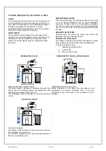
WATER CONNECTIONS
GENERAL
Piping must be designed with the least possible number of
bends and head variations. If the pressure chute of the
installation is above the useful prevalence of the pump, the
water delivery capacity is reduced as well as, as a
consequence, the thermal exchange and the yield.
INTERCEPTING VALVES
Install on the input and output of the user parts
(exchangers, coils, humidifiers, etc) So that it will be
possible to carry out all the service operations and possible
substitutions without emptying the installation.
PRESSURE AND TEMPERATURE INDICATOR
Install on the input and output of the user parts
(exchangers, coils, humidifiers, etc) So that it will be
possible to carry out all the service operations.
AUTOMATIC OR MANUAL ESCAPE VALVES
Install the highest points of tubes in a way that the air can
escape form the circuit.
BLEEDING COCK
Install them at the lowest points of the circuit, so as to allow
emptying.
LEAKAGE TESTS
Before performing the insulation of the tubes, carry out a
leakage test.
TUBE INSULATION
All tubes of water must be insulated so that to avoid the
formation of condensation and thermal dispersions along
the tubes themselves. Verify that the insulation is the
vapour coil type. The connections for the air escape and for
the emptying must be out of the insulating thickness to
assure the accessibilità.
CONNECTIONS SUPPORTS
The weight of the hydraulic connections must be supported
in the exterior of the unit so as not to stress the connections
of user devices (exchangers, coils, humidifiers, etc ) .
ANTI-VIBRATION DEVICES
In case of units with anti-vibration devices, it is necessary to
assemble elastic joints, even on water connections.
RISK OF FREEZE
If the unit and the relevant water connections are subject to
temperatures near 0°C:
•
mix the water of the system with glycol
•
protect the tubes with heating cables under the tubes
insulation
•
empty the system by verifying that:
o
no taps are closed so they can not trap the water,
even after emptying
o
there are no low points where the water can
stagnate even after emptying; blow if necessary
INTALLATION EMPTYING
The refilling of the water present in the installation increase
the oxidation phenomena and lime deposits.
If necessary empty only the interested system section and
anyway empty or refill the installation if necessary .
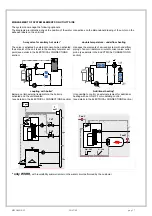
EXPANSION TANK
The installation must be kept at the right pressure by both
an expansion tank and a combined valve of pressure
reduction and discharge; if the components are present on
the unit, they must be installed on the installation. The
expansion tank must be dimensioned in function of the
water in the installation.
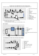
EXCHANGER USE SIDE
FILTER
It is very important for the water to be free of impurities. If it
is not, the efficiency of thermal exchange is diminished. In
worst cases, the exchanger can be irreparably damaged. If
the filter is not present on the machine, it must be
immediately installed upstream from the unit, in a position
which can be easily reached for cleaning
FLOW SWITCH
The flow switch must be present as a component of the
system, so as to ensure shutdown of the unit if water is not
circulating. It must be installed in a straight tract of the
tubes, not near the elbows, which can generate harmful
turbulence
UNFREEZABLE LIQUIDS
If the unit is used when the water temperature is lower than
+ 4°C, avoid the formation of ice by using unfreezable
liquids (ex. Ethilenic Glycol) in the necessary percentage.
The use must also be determined for room temperatures
near 0°C .
ANTIFREEZE HEATERS
If the unit is equipped with antifreeze heaters on the
exchanger side (standard or optional according to the
models), verify that they are electrically fed during periods
that the machine is stopped (night, weekends, long stops)
WASHING THE SYSTEM
Carefully wash the system by using clean water and
discharge it before connecting the unit.


