


M0G940E8-00 04/07/08
pag
57
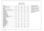
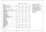
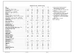
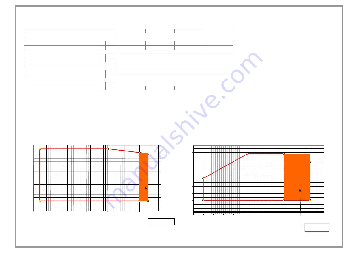
OPERATING LIMITS
Size
21 31 41 51
COOLING
EXTERNAL EXCHANGER
Max air intake temperature
1 °C
53
54
50
52
Max air intake temperature
2 °C
55
56
55
53
INTERNAL EXCHANGER
Max water inlet temperature
3 °C
24
Min. water outlet temperature
4 °C
3
HEATING
EXTERNAL EXCHANGER
Max air temperature inlet (WB)
5 °C
35
Min air inlet temperature (W.B.)
6 °C
-15
INTERNAL EXCHANGER
Min. water inlet temperature
7 °C
20
Max water outlet temperature
8 °C
61
59
60
60
(1) internal exchanger water = 23/18°C
Data refer to unit operating with fans at max. flow-rate. It follows an energy efficiency increase, but
also a sound pressure increase of about 2/3 dB(A).
(2) internal exchanger water = 12/7°C
Data refer to unit operating with fans at max. flow-rate. It follows an energy efficiency increase, but
also a sound pressure increase of about 2/3 dB(A).
(3) external exchanger air intake 30°C
Maximum exchanger inlet water temperature 32°C during max. 15 minutes, thanks to the variable
flow rate device for the circulator (standard).
(4) Antifreeze (std)
(5) Data referred to still air
(6) Internal Minimum water temperature at exchanger inlet 14°C during max. 15 minutes,
thanks to the variable exchanger water outlet temperature=39°C
(7) flow rate device of the circulator (standard).
(8) room temperature = 7°C (RH = 85%)
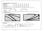
OPERATING LIMITS (COOLING)
OPERATING LIMITS (HEATING)
0
5
10
15
20
0
5
10
15
20
25
30
35
40
45
50
55
60
FRESH AIR TEMPERATURE (°C)
15
20
25
30
35
40
45
50
55
60
65
-20
-15
-10
-5
0
5
10
15
20
25
30
35
40
45
FRESH AIR TEMPERATURE (°C)
FANS AT 100%
FANS IN
MODULATION
W
A
T
E
R USE OUT
P
UT
T
E
M
PERAT
URE (°C)
W
A
T
E
R USE OUT
P
UT
T
E
M
PERAT
URE (°C)
Содержание WSAN-XPR 21
Страница 2: ......
Страница 25: ...M0G940E8 00 04 07 08 pag 25...
Страница 48: ...M0G940E8 00 04 07 08 pag 48...
Страница 49: ...M0G940E8 00 04 07 08 pag 49 TECHNICAL DATA...
Страница 59: ......


