CLIVET WSAN-XPR 21 Скачать руководство пользователя страница 36


M0G940E8-00 04/07/08 

pag 

36 


DEFROSTING  

The defrosting aim is to maintain the external coil free from ice during the winter mode : to do that the unit is periodically 
commuted in “summer” mode for few minutes and the fans are stopped.  
The defrosting phase is started when the evaporating pressure falls below a fixed value . A count starts and at its end, if the 
temperature on the coil is lower than the threshold, the defrosting starts .  
The count changes according to the external temperature and to the ice quantity on the coil ( by some indirect variables ) .  
When defrosting is complete, the unit returns automatically to the Winter mode. 
Defrosting is managed according to the external temperature and humidity in the air: 

• 

more humidity = frequent defrosting  

• 

external temperature next to 0°C = frequent defrosting 

By the EXTERNAL HUIDITY PROBE option cod PE2N0005 the defrosting is optimised according to the external temperature 
and humidity .  
 
CIRCULATION PUMP  
The pump is always activated with the units ON. 
The delivery capacity is variable to soften the thermal shock to the compressors when the plant temperature is close to the 
threshold limits. 
Delivery capacity depends on the intake temperature: 

• 

SUMMER: high water temperature reduces delivery  

• 

WINTER: low water temperature reduces delivery 

 
CIRCULATION PUMP – CONDENSER (RUNNING WATER) 
The pump is started BEFORE the compressor start and stopped AFTER the condenser stop . 
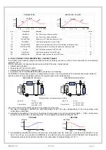
 
VENTILATION  
Fans are controlled with a variable speed: 

• 

in SUMMER, the speed increases according to the increase of external air temperature 

• 

in WINTER the speed increases according to the decrease of the external tempe 


SET POINT   


SUMMER - WINTER 

The thermoregulator manages two set points:  

• 

SUMMER set-point for cooling (parameter 32) 

• 

WINTER set-point for heating (parameter 33) 

The control is performed on the OUTLET TEMPERATURE, comparing it with the actual set-point value (visible at status 1). 


SET-POINT CALCULATION: 

• 

desired medium outlet water temperature = 7°C 

• 

Project temperature differential = 5°C (that is inlet water = 12°C) 

• 

¼ of the project temperature differential = 5 / 4 = 1.25°C  

• 

set-point to be set = 7 – 1.25  = 5.7°C 


SECONDARY SET POINT – ECO 

A secondary set point can be used with different levels to the “normal” set point. 
It is normally set to give lower energy consumption with respect to the comfort setting:  

• 

The SECONDARY SUMMER set point is higher than the SUMMER setting. 

• 

The SECONDARY WINTER set point is lower than the WINTER setting. 

It can be set according to individual requirements. 

• 

Secondary summer set-point parameter 29  

• 

Secondary winter set-point parameter 30 


It can be activated from the keyboard, supervisor unit or the remote control. To change it using the remote control refer to the 
ELECTRIC WIRING paragraph. 
 

MAINTENANCE  

This way, the plant can be kept within the operating limits even when the unit is OFF or on STANDBY, for example during the 
weekend or the night-time. 
Periodically the system activates the circulation pump, measures the water temperature and activates the compressor, if 
required, to take the water temperature to the set-point level. 


• 

Summer maintenance set-point  par 42 

• 

Winter maintenance set-point  par 43 


This function is activated by parameters 44 (activate summer maintenance level) and 45 = 1 (activate winter maintenance 
level). In this mode on the service keypad is displayed : STB 

Содержание WSAN-XPR 21

Страница 1: ...WSAN XPR 21 31 41 51 AIR TO WATER HEAT PUMP FOR OUTDOOR INSTALLATION Installation and Use Manual M0G940E8 00 04 07 08...

Страница 2: ......

Страница 3: ...LIMINARY CHECKS 32 REFRIGERANT SYSTEM 32 WATER SYSTEM 32 ELECTRICAL SYSTEM 32 VERIFy tensions absorptions 33 UNIT EQUIPPED WITH SCROLL COMPRESSORS 33 REMOTE INPUT CONFIGURATIONS 33 SETTING THE SET POI...

Страница 4: ...AL NUMBER This provides unique identification of the machine It makes it possible to trace the specific features of the unit and to identify the components installed in it Without this number it is no...

Страница 5: ...2 1 3 4 5 6 WINTER the cooling cycle makes it possible to absorb energy heat at low temperature from the external environment and to transfer it to the area to be heated 1 The compressor compresses t...

Страница 6: ...aintaining the system at a safety temperature in WINTER MAINTENANCE function Put the unit in OFF parameter 45 must be 1 yellow led is flashing Minimize the consumptions maintaining the system at a saf...

Страница 7: ...g Control parameter parametro 43 Modify the water temp in MAINTENANCE cooling Control parameter 42 Only by SERVICE keypad A L A R M S T A T U S S E T COMMON CAUSES OF SHUTDOWN 1 coils dirty clogged by...

Страница 8: ...does not respect the instructions given in this manual will cause the warranty to lapse INTENDED USE The unit must only be used for the specific purpose it was designed The unit is designed to cool h...

Страница 9: ...zed entry GENERAL RISKS A smell of burning smoke or other indications of serious irregularity could signal the onset of situations liable to cause damage to persons or property or to the unit itself I...

Страница 10: ...er Chart No FRIG 8 Product R 410A Identification of the supplier See heading or bottom of page No of emergency telephone See heading or bottom of page 02 Composition information on ingredients Substan...

Страница 11: ...ed from the driver compartment Verify that the driver is informed on the potential risk of the load and that he knows what to do in case of an accident or emergency Before starting the transport verif...

Страница 12: ...ressure of the circuits can assume values which activate the safety valves HANDLING The operation of handling the unit must be carried out respecting the instructions of the safety norms in force Legi...

Страница 13: ...nt and can only be placed there The anti vibration devices must therefore be placed in accordance with the instructions provided with them and with the dimensional drawings in which the support points...

Страница 14: ...ximum depth that snowfall might reach A 2 A Tree 1 3 2 1 elastic joint 2 floating floor 3 soundproofing Consider clearances and direction of expelled air Keep the coil clean Avoid zones with leaves di...

Страница 15: ...tubes insulation empty the system by verifying that o no taps are closed so they can not trap the water even after emptying o there are no low points where the water can stagnate even after emptying b...

Страница 16: ...ys ON OFF sanitary H2O 3 sanitary boiler 4 fancoil 5 3 ways radiant panels 6 radiant pump 7 radiants 8 pump for more details see the ELECTRICAL DATA section and the SYSTEM SCHEMA WITH ACCESSORIES at p...

Страница 17: ...ing to the characteristics of the protections used SIGNALS DATA LINES Do not overpass the maximum power allowed which varies according to the type of signal Lay the cables far from power cables or cab...

Страница 18: ...TERMINAL Permits setting the unit function modes cooling heating ECO and to display the alarms ELECTRIC REFRIGERATOR WATER This is standard on certain types of unit L N 91 92 STA TU S SET ALA RM 2 1 R...

Страница 19: ...tic hot water boiler page 30 1 ON OFF FROM REMOTE CONTROL Generally the unit is delivered with bridged terminals if the control is not used bridge terminals 2 CHANGING FROM SUMMER TO WINTER USING THE...

Страница 20: ...s disabled due to an external temp lower than par 180 1 1 MAIN ADJUSTMENT UNIT IN HEATING MODE in heat pump mode the compressor is disabled 2 1 POWER LIMITATION ACCORDING TO EXTERNAL TEMPERATURE the f...

Страница 21: ...econd set point Refer to the wiring diagram to identify the corresponding terminals PLUG IN module 26 25 24 23 22 30 29 28 27 CN3 1 3 5 7 9 11 2 4 6 8 10 12 par Description Meaning value 49 Comando2 S...

Страница 22: ...HEATING LIMIT avoids dew overheating ATTENTION to prevent dew in summer or superheating in winter it is very important to fit an external device and interface it with the unit that in case of signall...

Страница 23: ...orresponding signal of the summer MIN correction 4 140 PlugInEn Enables PLUG IN presence 1 YES 0 NO SET POINT CURVE IN COOLING SET POINT CURVE IN HEATING mA P 23 P 24 COMP MAX P22 COMP 0 SET POINT mA...

Страница 24: ...conductors twisted and shielded Section of conductor 0 22mm 2 0 35mm 2 Nominal capacity between conductors 50 pF m nominal impedance 120 Recommended cable BELDEN 3105 A TYPE OF NETWORK The serial lin...

Страница 25: ...M0G940E8 00 04 07 08 pag 25...

Страница 26: ...DRAULIC DIAGRAM WSAN XPR DOMESTIC HOT WATER RADIANT PANELS UR BT1 R E WSAN XPR RS 485 AP5 GN D AP5 ACS BT2 DOMESTIC HOT WATER KIT FLEXIBLE PIPE KIT PEE20016 1 x BT1 R E 1 x 1 x 1 x ACS 1 x RS 485 AP5...

Страница 27: ...G940E8 00 04 07 08 pag 27 WIRING DIAGRAM BT2 92 91 90 88 87 XC UR BT1 R E GND RS485 1 3 6 2 83 61 87 XC ACS 400 3 50 N N L3 L2 L1 26 L H GND XC 21 81 RS 485 AP5 GND RS485 61 86 ACS ACS Hydraulic diagr...

Страница 28: ...HYDRAULIC DIAGRAM WSAN XPR DOMESTIC HOT WATER FAN COILS BT1 R E UR RS 485 AP5 GN D AP5 WSAN XPR ACS BT2 DOMESTIC HOT WATER KIT FLEXIBLE PIPE KIT PEE20016 1 x BT1 R E 1 x 1 x 1 x ACS 1 x RS 485 AP5 GN...

Страница 29: ...G940E8 00 04 07 08 pag 29 WIRING DIAGRAM UR BT1 R E GND RS485 1 3 6 2 61 87 81 XC ACS RS485 400 3 50 N N L3 L2 L1 83 L H GND XC 21 25 92 91 90 88 87 XC RS 485 AP5 GND 61 86 ACS BT2 ACS Hydraulic diagr...

Страница 30: ...6 25 24 23 22 30 29 28 27 ON OFF BT2 DOMESTIC HOT WATER KIT HYDRAULIC CIRCUIT BREAKER HYDRAULIC CIRCUIT BREAKER PEE20016 1 x BT1 R E 1 x 1 x 1 x ACS 1 x RS 485 AP5 GND KSAX 1 x KTFL1X 2 x BOILER MANAG...

Страница 31: ...P5 GND ON OFF 25 21 26 83 84 81 87 61 UR GND RS485 RS485 3 2 6 1 SMR TS 6 2 1 3 7 F N PE 61 6 BT5 XC2 XT3 29 61 55 XT3 29 34 XT3 F PE N 85 61 86 ACS XC3 8 9 SDCV PE 61 6 7 81 5 4 27 28 30 XT3 25 23 81...

Страница 32: ...osition Check that there is no air in the circuit If required bleed it using the vent valves in the system When using antifreeze solutions make sure the glycol percentage is suitable for the type of u...

Страница 33: ...ated ON OFF etc as given in the instructions in the ELECTRIC WIRING chapter SETTING THE SET POINT Check if it is necessary to modify the set points shown in the CONTROL chapter EVAPORATOR WATER FLOW R...

Страница 34: ...CAL CONNECTIONS paragraph CHARACTERISTICS THERMOREGULATION The thermoregulation is based on the OUTLET temperature The unit is dimensioned for a determined TOTAL HEAD between input and output water te...

Страница 35: ...ating with low external temperatures so with a reduced charge is possible to obtain the internal comfort also with set point higher than standard obtaining an higher energetic efficiency CORRECTION AC...

Страница 36: ...INTER the speed increases according to the decrease of the external tempe SET POINT SUMMER WINTER The thermoregulator manages two set points SUMMER set point for cooling parameter 32 WINTER set point...

Страница 37: ...es that manage sanitary hot water production the status is displayed with the WINTER and SUMMER operation LEDs WINTER SUMMER ON FLASHING ON OFF The ON OFF control from the keyboard allows activating o...

Страница 38: ...System charged with water Radiant panel water probe CCMP VENT Antifreeze alarm Coil flow probe HP1 Pre Alarm Antifreeze PREAlarm External probe BP1 Pre Alarm Pump alarm Pressure 1 probe C1 PREAlarm W...

Страница 39: ...nt 5 7 C 33 Winter Set Point 41 2 C 42 Summer Set Point Maintenance 20 C 43 Winter Set Point Maintenance 30 C 44 Enables Summer Maintenance 0 num 45 Enables Winter Maintenance 0 num 77 Antifreeze heat...

Страница 40: ...12 Coil temperature C 13 Condensing pressure Bar 14 Fan Valve 1 percentage 0 100 15 Heater output temperature 18 Water Reset signal value 4 20 mA 19 Outdoor temperature C 20 Outdoor Humidity 0 100 21...

Страница 41: ...E 00 Serial faulty comunicazione tastiera scheda base Auto E 1 Faulty or disconnected water inlet probe Auto E 2 Faulty or disconnected water outlet probe Auto E 3 Faulty or disconnected radiating pan...

Страница 42: ...m the surface Using an air pressure gun clean the aluminum surface of the battery Be careful to direct the air in the opposite direction of the fan air movement Hold the gun parallel to the fins to av...

Страница 43: ...s as well Refer to local actuation norms In Italy refer to the Ministerial Decree of 1 st December 2004 no 329 and following modifications which defines the performances to be executed the units of 1...

Страница 44: ...15 8 25 57 20 8 35 71 25 8 44 22 30 8 51 59 35 8 58 09 40 8 63 92 1 0 37 03 6 0 4 10 11 0 13 40 16 0 26 01 21 0 36 08 26 0 44 53 31 0 51 86 36 0 58 34 41 0 64 14 1 2 34 84 6 2 3 24 11 2 13 97 16 2 26...

Страница 45: ...in cooling 1 low air temperature see operating limits 2 low water temperature see operating limits 3 insufficient water flow to the exchanger high thermal difference between input and output 4 not CON...

Страница 46: ...air temperature see operating limits 2 high water temperature see operating limits 3 insufficient water flow to the exchanger high thermal difference between input and output 4 not CONSTANT flow for...

Страница 47: ...must be stored in special containers When recovering the substances present in the unit all measures must be taken to avoid damaging persons and things and polluting the surrounding area Awaiting dism...

Страница 48: ...M0G940E8 00 04 07 08 pag 48...

Страница 49: ...M0G940E8 00 04 07 08 pag 49 TECHNICAL DATA...

Страница 50: ...onsidered In the event of multiple units the functional clearances must be doubled Size 21 M mm 349 N mm 161 O mm 176 P mm 160 Length mm 800 Depth mm 300 Height mm 930 W1 kg 15 W2 kg 32 W3 kg 14 W4 kg...

Страница 51: ...nces for operation and maintenance The following sketch describes the minimum clearances to be considered In the event of multiple units the functional clearances must be doubled Size 31 41 M mm 334 3...

Страница 52: ...ered In the event of multiple units the functional clearances must be doubled Size 51 M mm 343 N mm 167 O mm 144 P mm 192 Length mm 800 Depth mm 300 Height mm 1370 W1 kg 19 W2 kg 39 W3 kg 26 W4 kg 51...

Страница 53: ...1 kPa 64 85 70 85 EXTERNAL SECTION FANS Type of fans 8 AX AX AX AX Number of fans Nr 2 2 2 3 Standard air flow 1 l s 1014 1030 1270 1764 Installed unit power kW 0 09 0 09 0 115 0 12 CONNECTIONS Water...

Страница 54: ...5 C 1 kPa 46 70 41 69 EXTERNAL SECTION FANS Type of fans 9 AX AX AX AX Number of fans Nr 2 2 2 3 Standard air flow 1 l s 1014 1030 1270 1764 Installed unit power kW 0 09 0 09 0 115 0 12 CONNECTIONS Wa...

Страница 55: ...ns 8 AX AX AX AX Number of fans Nr 2 2 2 3 Standard air flow 1 l s 1014 1030 1270 1764 Installed unit power kW 0 09 0 09 0 115 0 12 CONNECTIONS Water fittings 1 GAS 1 GAS 1 GAS 1 GAS HYDRAULIC CIRCUIT...

Страница 56: ...EXTERNAL SECTION FANS Type of fans 9 AX AX AX AX Number of fans Nr 2 2 2 3 Standard air flow 1 l s 1014 1030 1270 1764 Installed unit power kW 0 09 0 09 0 115 0 12 CONNECTIONS Water fittings 1 GAS 1 G...

Страница 57: ...to unit operating with fans at max flow rate It follows an energy efficiency increase but also a sound pressure increase of about 2 3 dB A 3 external exchanger air intake 30 C Maximum exchanger inlet...

Страница 58: ...n the external exchanger having clean plates fouling factor 1 For different fouling factor values multiply the performance by the coefficients shown in the table F1 Cooling capacity correction factors...

Страница 59: ......

Страница 60: ...24 info clivet nl CLIVET TFAIRSYSTEMS P LTD Malur INDIA Tel 91 8151 232683 5 Fax 91 8151 232684 info clivettfa com CLIVET SPA BUREAUDE LIAISON EN FRANCE Verrier s le Buisson FRANCE Tel 33 0 1 69 20 25...

Отзывы: