background image

13

CHANGING THE KEEL OFFSET

(Enable engineering mode, see page 11)

The keel offset represents the distance between the transducer itself
and the bottom of the keel. When a keel offset is stored, all
measurements (including alarms) are shown as if measured from the
bottom of the keel instead of the transducer. If, for example, the bottom
of the keel is 0.4metres below the depth of the transducer in the hull,
setting the offset to 0.4m will ensure that the readings displayed show
the depth below the keel instead of from the transducer.

The DEEP and SHALL buttons are used separately to adjust the
keel offset value in the range 0 to 2.5m (8.3ft.), In steps of 0.1m
(0.5ft.). No repeat is embodied on the keys because of the small
range of adjustment. Pressing DEEP increases the keel offset
depth, and pressing SHALL reduces the keel offset depth.
Press the ILLUM key to return to normal echo sounding mode.

CHANGING BETWEEN KEEL AND SURFACE OFFSET

(Enable engineering mode, see page 11)

It is sometimes preferable to measure the depth from the surface
instead of the transducer or keel. If, for example, the transducer is
0.3m below the surface, setting a surface offset of 0.3m will ensure
that the readings displayed show the depth below the surface
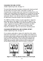
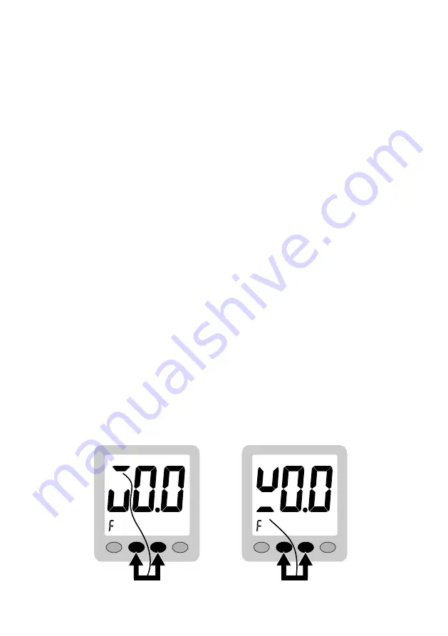
instead of from the transducer itself. Pressing the ENTER and
DEEP buttons together switches between the keel depth and
surface depth measurement modes, as shown on Figure 9.

ENTER

SHALL

DEEP

ILLUM

METRES

ENTER

SHALL

DEEP

ILLUM

METRES

Figure 9 - Switching Between Surface and Keel Depth.

Содержание ECHO SOUNDER

Страница 1: ...ENTER SHALL DEEP ILLUM CLIPPER DUET CLIPPER ECHO SOUNDER METRES DEPTH CLIPPER DEPTH...

Страница 2: ......

Страница 3: ...DEPTH ALARM SETTINGS ACTIVATING DEPTH ALARMS CHANGING THE GAIN DELAY SETTING ENGINEERING MODE SWITCHING BETWEEN FEET AND METRES CHANGING THE KEEL OFFSET CHANGING BETWEEN KEEL AND SURFACE OFFSET CHANGI...

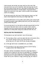
Страница 4: ...ole in the panel 87mm wide and 67mm deep Bring the wiring through the hole in the panel and connect the black wire to negative and red to positive See Figure 1 It is wise to use a fused supply to prov...

Страница 5: ...t even if they later have to rise to connect to the vessel s supplies Doing so prevents any water that might get onto the cables from running back along the cables and into the unit INSTALLING THE TRA...

Страница 6: ...rs or sudden changes in hull profile which could disrupt the signal To test the suitability of the location when the vessel is in the water at a reasonable depth press a little sticky chewing gum on t...

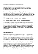
Страница 7: ...ay from any possible source of electrical interference GETTING STARTED When the Clipper Echo sounder is first turned on it automatically performs a number of self test processes and after a brief dela...

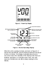
Страница 8: ...BRIGHTNESS BACKLIGHT BRIGHTNESS DEPTH RATE INDICATOR DEPTH IS NOT MORE THAN DEEP ALARM DEPTH Figure 3 Normal Operating Display When the unit is working normally as shown on Figure 3 it shows the word...

Страница 9: ...is changing is less than about 60 feet per minute 20 metres per minute the central bar is lit When the rate is higher either the left or right arrow head is lit The depth rate indications are the only...

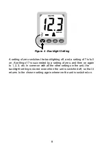
Страница 10: ...and a setting of 7 is full on A setting of 7 is succeeded by a setting of zero and then on again to 1 2 3 etc In common with all the other settings in the unit the backlight setting is stored even wh...

Страница 11: ...button to make the deep alarm depth shallower If the SHALL button is pressed steadily the setting reduces continually in 1 5 foot or 0 5 metre steps If the DEEP button is pressed steadily the setting...

Страница 12: ...the shallow alarm depth setting whereupon the display returns to measuring depth ACTIVATING DEPTH ALARMS At any time the deep and shallow alarms may be activated or de activated together at the set l...

Страница 13: ...lections from being misinterpreted sweeping the gain can be delayed until a pre set depth is reached The delay is called the sensitivity threshold and can be viewed at any time during normal operation...

Страница 14: ...ing feet and metres The chosen setting is displayed at the bottom right of the window The setting is stored for all subsequent use and can be switched back again if desired The operating mode feet or...

Страница 15: ...5ft No repeat is embodied on the keys because of the small range of adjustment Pressing DEEP increases the keel offset depth and pressing SHALL reduces the keel offset depth Press the ILLUM key to re...

Страница 16: ...h capability of the unit 100m A new measurement of depth is thus available within the unit seven times a second In turbulent conditions or in the presence of high levels of noise such as outboard moto...

Страница 17: ...false depth alarms if interference is present by ensuring that the alarm depth has been consistently crossed before the alarm is sounded Enable engineering mode see page 11 The factory pre set displa...

Страница 18: ...eturn again whenever the unit is switched on Returning to configuration setting from normal echo sounding is not available If further configuration changes are desired they can be made only by switchi...

Страница 19: ......

Страница 20: ...prudently and check its operation from time to time against other data Inspect the installation from time to time and seek advice if any part thereof is not fully seaworthy Nasa Marine Ltd warrants th...

Отзывы: