climecon.fi
© Climecon
2
Installation manual ECO-W
3. Connection
1.
NOTE! Run the 230 V supply voltage to the device through a double-pole switch. Connect the supply voltage to connectors
N and L in the electronics section of the terminal device, as shown in Figures 3.2 and 3.3.
2.
Connect the ground to the terminal device’s separate ground connector, as shown in Figures 3.2 and 3.3.
3.
Connect the ECO series terminal device to the controller with the data cable, as shown in Figures 3.2 and 3.3.
4.
Activate the terminator by moving the termination jumper to the ON position
in the first and last device of the bus, as shown in Figure 3.3.
5.
DIP switch operation:
• One thermostat controls one terminal device: there is no need to change the position of the DIP switches.
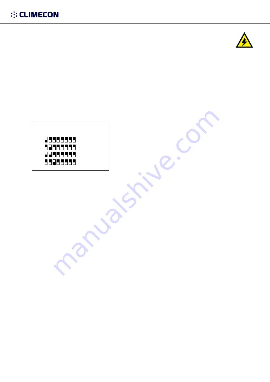
• One thermostat controls 2–4 terminal devices: Position the DIP switches as shown in the figure.
• The air heater is controlled with a 230 V supply voltage without the ECO-T controller, as shown in Figure 3.4:
move the DIP switch No 8 to the ON position.
NOTE! Electrical connections may only be made by a professional electrician.
WARNING! The supply air device carries a voltage of 230 V.
U = 230 V In = 1.7 A
The connect signal D-/D+ is RTU.
For the BMS connection settings, see Appendix 1. ECO ModBus map.
The recommended data cable between the controller and the air heater is e.g., NOMAK 2x2x0.5+0.5
230VAC
CONTROL
Modbus
TERMINATION
OFF-ON
DIP1-8:
Modbus-ID
L
N
N
L
X3
X2
X1
230VAC
CONTROL
Modbus
TERMINATION
OFF-ON
OFF/ON
DIP1-8:
Modbus-ID
L
N
N
L
X3
X2
X1
D- D+ V
T
B A
CONTROL BUS
T
OFF ON
Bus
termination
by jumper
OFF ON
Bus
termination
by jumper
CONTROL Modbus-ID
ID: 1-4
1 =
2 =
3 =
4 =
Figure 3.1


