3
1. Application Overview
1.1. Parts Identification
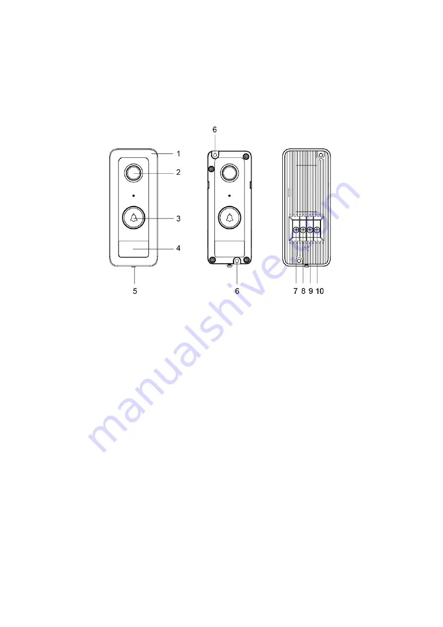
Front View
Front View
(cover removed)
Back View
1. Protective Cover
2. Camera Lens
3. Function Button / LED Indicator (Blue / Amber)
4. IR Lens
5. Cover Fixing Screw
6. Mounting Hole
7. 12~24V DC/AC Power Input
Please note the torque on the screw should be less than 24.5 Nm (2.5 kg-m).
8. 12~24V DC/AC Power Input
Please note the torque on the screw should be less than 24.5 Nm (2.5 kg-m).
9. Reserved
10. Reserved
1.2. The Power Supply
The VDP uses 12~24V DC/AC power as its power source. Turn off mains power first.
Loosen the two screws of the 12~24V DC/AC Power Input, and save the screws for later
use. Connect wires to the inputs on the rear side of the back cover
*
; install the VDP to
power on the device.
*Note:
It is recommended to use wire with a diameter less than 15mm to connect to the
power input. The torque on the screw should be less than 24.5 nm (2.5 kg-m).


