Schematic Diagrams
B - 1
B.Schematic Diagrams
Appendix B: Schematic Diagrams
Table B - 1
SCHEMATIC
DIAGRAMS
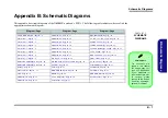
This appendix has circuit diagrams of the
N650DU
notebook’s PCB’s. The following table indicates where to find the
appropriate schematic diagram.
Diagram - Page
Diagram - Page
Diagram - Page
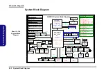
System Block Diagram - Page B - 2
5V, 5VS, 3.3V, 3VS, 3.3VA - Page B - 33
VCORE Output Stage - Page B - 35
VCCGT Output Stage, VCCSA - Page B - 36
DDR 1.2V, 0.6VS, 2.5V - Page B - 38
DDR4 CHA SO-DIMM_0 - Page B - 10
M.2 SSD, CCD, Fan, Audio, LED - Page B - 25
DDR4 CHB SO-DIMM_0 - Page B - 11
HDD, PWR LED, LID - Page B - 28
ODD to HDD Board - Page B - 44
LAN, Card Reader - Page B - 30
Version Note
The schematic dia-
grams in this chapter
are based upon ver-
sion 6-7P-N6505-004.
If your mainboard (or
other boards) are a lat-
er version, please
check with the Service
Center for updated di-
agrams (if required).
Содержание N650DU Series
Страница 1: ...N650DU ...
Страница 2: ......
Страница 3: ...Preface I Preface Notebook Computer N650DU Service Manual ...
Страница 24: ...Introduction 1 12 1 Introduction ...
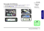
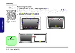
Страница 48: ...Disassembly 2 24 Removing the CCD 2 Disassembly ...
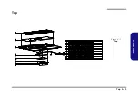
Страница 51: ...Top A 3 A Part Lists Top Figure A 1 Top ...
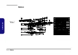
Страница 52: ...A 4 Bottom A Part Lists Bottom Figure A 2 Bottom ...
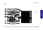
Страница 53: ...LCD A 5 A Part Lists LCD Figure A 3 LCD ...
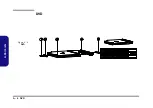
Страница 54: ...A 6 DVD A Part Lists DVD Figure A 4 DVD ...
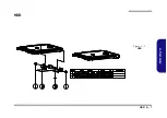
Страница 55: ...HDD A 7 A Part Lists HDD Figure A 5 HDD ...
Страница 56: ...A 8 2nd HDD A Part Lists 2nd HDD Figure A 6 2nd HDD ...
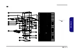
Страница 57: ...MB A 9 A Part Lists MB Figure A 7 HDD ...
Страница 58: ...A 10 A Part Lists ...
Страница 104: ...Schematic Diagrams B 46 B Schematic Diagrams ...

