background image

Disassembly

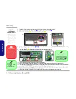
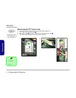
2 - 14 Removing the TV Tuner Card

2.Disassembly

Removing the TV Tuner Card

1.

Turn off the computer, and turn it over, remove the battery (

page 2 - 5

).

2.

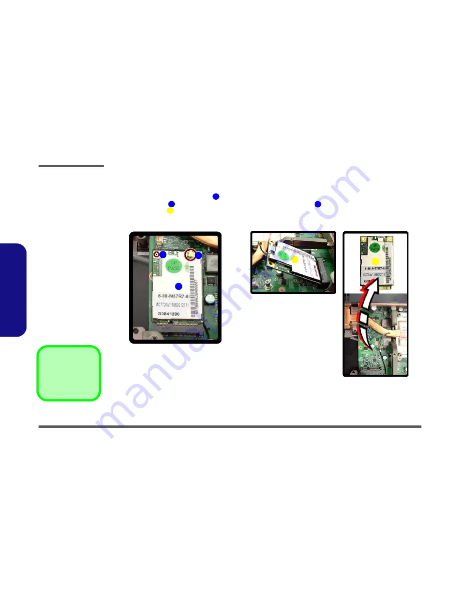
The TV tuner card is visible at point 

3.

Remove the screw 

 from the TV tuner module and disconnect the cable 

.

4.

The TV tuner card 


will pop-up and and you can remove it.

.

Figure 10

TV Tuner Card 

Removal 


a. Remove the screws and

disconnect the cable.

b. The TV tuner card will

pop up and remove it.

1

2

3

4

b.

a.

2

3

1

4

4

4. TV tuner card 

1  Screw

Содержание M980NU

Страница 1: ......

Страница 2: ......

Страница 3: ...Preface I Preface Notebook Computer M980NU Service Manual ...

Страница 4: ...hole or in part be reproduced translated transmitted or reduced to any machine readable form without prior consent from the vendor manufacturer or creators of this publica tion except for copies kept by the user for backup purposes Brand and product names mentioned in this publication may or may not be copyrights and or registered trademarks of their respective companies They are mentioned for ide...

Страница 5: ...sic information for servicing and or upgrading components of the M980NU series notebook PC The following information is included Chapter 1 Introduction provides general information about the location of system elements and their specifications Chapter 2 Disassembly provides step by step instructions for disassembling parts and subsystems and how to upgrade elements of the system Appendix A Part Li...

Страница 6: ...other than a cordless type during an electrical storm There may be a remote risk of elec trical shock from lightning 3 Do not use the telephone to report a gas leak in the vicinity of the leak 4 Use only the power cord and batteries indicated in this manual Do not dispose of batteries in a fire They may explode Check with local codes for possible special disposal instructions 5 This product is int...

Страница 7: ... down properly and don t forget to save your work Remember to periodically save your data as data may be lost if the battery is depleted Do not expose the computer to any shock or vibration Do not place it on an unstable surface Do not place anything heavy on the computer Do not expose it to excessive heat or direct sunlight Do not leave it in a place where foreign matter or mois ture may affect t...

Страница 8: ... its purpose If you do not have access to a compatible outlet have a qualified electrician install one When you want to unplug the power cord be sure to disconnect it by the plug head not by its wire Make sure the socket and any extension cord s you use can support the total current load of all the connected devices Before cleaning the computer make sure it is disconnected from any external power ...

Страница 9: ...ur hands or metal objects Battery Guidelines The following can also apply to any backup batteries you may have If you do not use the battery for an extended period then remove the battery from the computer for storage Before removing the battery for storage charge it to 60 70 Check stored batteries at least every 3 months and charge them to 60 70 Battery Disposal The product that you have purchase...

Страница 10: ...ng manual for additional information User s Manual on CD This describes the notebook PC s features and the procedures for operating the computer and its ROM based setup pro gram It also describes the installation and operation of the utility programs provided with the notebook PC ...

Страница 11: ... 7 Removing the System Memory RAM 2 9 Removing the VGA Card 2 11 Installing the VGA Card 2 13 Removing the TV Tuner Card 2 14 Part Lists A 1 Part List Illustration Location A 2 Top with Fingerprint A 3 Top without Fingerprint A 4 Bottom A 5 LCD A 6 Mainboard A 7 Blu Ray Combo A 8 DVD Super Multi A 9 Schematic Diagrams B 1 System Block Diagram B 2 PENRYN 1 2 B 3 PENRYN3 2 2 B 4 MCP79 FSBI B 5 MCP79...

Страница 12: ...5V B 35 Power 1 0VS B 36 Power 3 3V 5V B 37 Power Charger DC In B 38 Single HDD Board B 39 Dual HDD Board B 40 Audio Board B 41 Power Button Board B 42 Click FP Board B 43 Logo LED Board B 44 Game Key Board B 45 TouchPad LED Board B 46 Front R Side LED Board B 47 Front L Side LED Board B 48 Back L Side LED Board B 49 Touch Sensor Board A B 50 Touch Sensor Board B B 51 CIR Board B 52 Finger Board B...

Страница 13: ...shipped with the computer Operating systems e g Windows XP Windows Vista etc have their own manuals as do application software e g word processing and database programs If you have questions about those programs you should consult those manuals The M980NU series notebook is designed to be upgradeable See Disassembly on page 2 1 for a detailed description of the upgrade procedures for each specific...

Страница 14: ... Cache 1066MHz FSB 25W P8700 2 53 GHz 3MB On die L2 Cache 1066MHz FSB 25W Core Logic MCP79 SLI Chipset Display 18 4 Full HD 1920 1080 TFT LCD Memory Two 64 bit wide DDRIII DDR3 data channels Two 204 Pin SO DIMM Sockets Supporting DDRIII DDR3 1066MHz 1333MHz Memory Modules Memory Expandable up to 4GB Video Adapter nVIDIA GeForce GTX 280M SLI PCIe Video Card 1GB GDDR3 Video RAM On Board Supports PCI...

Страница 15: ...latform Module V1 2 Factory Option Communication Built In Giga Base TX Ethernet LAN Bluetooth 2 1 EDR Enhanced Data Rate Module Factory Option Intel WiFi Link 5300 Series 3 3 802 11a g n Wireless LAN PCIe interface Mini Card Module Option Intel WiFi Link 5100 Series 1 2 802 11a g n Wireless LAN PCIe interface Mini Card Module Option 3rd Party 802 11b g Wireless LAN PCIe interface Mini Card Module ...

Страница 16: ...dule Blu Ray Combo Drive Module Intel WiFi Link 5300 5100 Series 3 3 1 2 802 11a g n Wireless LAN PCIe Interface Mini Card Module 3rd Party 802 11b g Wireless LAN PCIe Interface Mini Card Module Bluetooth 2 1 EDR Enhanced Data Rate Module Factory Option 2 0M or 3 0M Pixel USB 2 0 PC Camera Module Factory Option Fingerprint Reader Module Factory Option Mini Card TV Tuner Module with USB Interface F...

Страница 17: ...External Locator Top View with LCD Panel Open Figure 1 Top View 1 Optional Built In PC Camera 2 LCD 3 LED Status Indicators 4 Touch Sensor Instant Keys 5 8 Gaming Keys 6 Keyboard 7 TouchPad and Buttons 8 Fingerprint Reader Module optional 9 LED Power Indicators 2 1 6 7 8 4 5 3 9 ...

Страница 18: ...Ds 2 Speakers 3 LED Power Indicators 4 Consumer Infrared Transceiver enabled with optional TV Tuner only Figure 3 Right Side Views 5 Headphone In Jack 6 Microphone In Jack 7 Line In Jack 8 S PDIF Out Jack 9 Cable CATV Antenna Jack 10 Combined eSATA USB Port 11 USB 2 0 Port 12 Security Lock Slot 13 Power Button 2 3 2 1 1 4 6 5 7 8 9 11 12 13 10 ...

Страница 19: ...r Left Side Rear View Figure 4 Left Side View 1 DVI Out Port 2 2 USB 2 0 Ports 3 RJ 45 LAN Jack 4 HDMI Out Port 5 7 in 1 Card Reader 6 ExpressCard Slot 7 Mini IEEE 1394 Port 8 Optional Device Drive Bay 1 2 3 4 5 8 6 7 Figure 5 Rear View 9 Color LEDs 10 Speakers 11 DC In Jack 11 9 10 9 ...

Страница 20: ... View Figure 6 Bottom View 1 Sub Woofer 2 Fan Outlet Intake 3 Component Bay Cover 4 Battery Secondary HDD Bay HDD3 5 Primary HDD Bay HDD1 2 Overheating To prevent your com puter from overheating make sure nothing blocks the vent fan in takes while the com puter is in use 1 2 4 5 3 2 2 ...

Страница 21: ...ction Mainboard Overview Top Key Parts 1 9 1 Introduction Mainboard Overview Top Key Parts 1 2 2 3 Figure 7 Mainboard Top Key Parts 1 North Bridge 2 Memory Slots DDR3 So DIMM 3 Mini Card Connector WLAN Module ...

Страница 22: ...duction 1 10 Mainboard Overview Bottom Key Parts 1 Introduction Mainboard Overview Bottom Key Parts Figure 8 Mainboard Bottom Key Parts 1 CPU Socket 2 VGA Socket 3 Mini Card Connector TV Module 4 6 5 1 3 2 2 ...

Страница 23: ...e Connector 4 Inverter Cable Connector 5 LED Cable Connector 6 Subwoofer Connector 7 Power Button Connector 8 Game Key Cable Connector 9 Bluetooth Module Connector 10 LED Cable Connector 11 Touch Pad Connector 12 USB Cable Connector 13 Audio Cable Connector 14 SW Connector 15 Fingerprint Connector 16 Keyboard Cable Connector 17 Audio Cable Connector 1 3 2 5 7 6 8 9 10 11 13 4 12 14 15 17 16 ...

Страница 24: ...Introduction 1 12 Mainboard Overview Bottom Connectors 1 Introduction Mainboard Overview Bottom Connectors Figure 10 Mainboard Bottom Connectors 1 Battery Connector 2 3 4 1 ...

Страница 25: ...embly process easier each section may have a box in the page margin Information contained under the figure will give a synopsis of the sequence of procedures involved in the disassembly procedure A box with a lists the relevant parts you will have after the disassembly process is complete Note The parts listed will be for the dis assembly procedure listed ONLY and not any previous disassembly step...

Страница 26: ...c ing the connection make sure the connector is oriented in the same way The pin1 side is usually not indicated Pressure sockets for multi wire connectors To release this connector type grasp it at its head and gently rock it from side to side as you pull it out Do not pull on the wires themselves When replacing the connection do not try to force it The socket only fits one way Pressure sockets fo...

Страница 27: ... Do not pull on the wire 6 Peripherals Turn off and detach any peripherals 7 Beware of static discharge ICs such as the CPU and main support chips are vulnerable to static electricity Before handling any part in the computer discharge any static electricity inside the computer When handling a printed circuit board do not use gloves or other materials which allow static electricity buildup We sugge...

Страница 28: ...battery page 2 5 To remove the Optical Device 1 Remove the battery page 2 5 2 Remove the Optical device page 2 6 To remove the HDD 1 Remove the battery page 2 5 2 Remove the HDD page 2 7 To remove the System Memory 1 Remove the battery page 2 5 2 Remove the System Memory page 2 9 To remove the VGA card 1 Remove the battery page 2 5 2 Remove the VGA card page 2 11 To remove the TV Tuner Card 1 Remo...

Страница 29: ... safety reasons it is best to remove the battery 1 Turn the computer off and turn it over 2 Loosen screws and carefully lift the battery up Figure b 3 Remove the battery from the battery bay 4 Battery 3 Screws 1 3 4 Figure 1 Battery Removal a Loosen screws b Release the battery c Lift the battery out of the bay as indicated a 4 b 1 2 3 c 4 ...

Страница 30: ...d remove screws and remove the bay cover 3 Remove screw 4 Use the screwdriver to push the optical device out of the computer at point 5 Reverse the process to install the new device Figure 2 Optical Device Removal a Remove the screws b Remove the cover c Remove the screw and push the optical device out of the computer at point 8 1 2 3 4 6 5 3 Hard Disk Bay Cover 6 Optical Device 3 Screws 1 2 4 a b...

Страница 31: ... cover 4 Remove screws and pull the tab to disconnect the connector from hard disk assembly 5 Lift the hard disk assembly out of the computer 6 Remove screws depending on how many hard disks you have installed in the assembly 7 Separate the hard disk board connector from the case 8 Separate the hard disk s from the case 9 Reverse the process to install a new hard disk s Figure 3 HDD Assembly Remov...

Страница 32: ... of the arrow 5 Lift the hard disk assembly out of the compartment 6 Remove the screws to release the hard disk from the case 7 Reverse the process to install any new hard disk s 6 Hard Disk Assembly 11 Hard Disk Case 8 Screws Figure 4 Secondary HDD Assembly Removal a Remove the screws and slide the hard disk as sembly in the direction of the arrow b Lift the hard disk assem bly out off the comput...

Страница 33: ...puter and turn it over and remove the battery page 2 5 2 Remove screws from the bottom of the computer 3 Turn the computer over open the Lid LCD and carefully a cable is connected to the underside of the LED cover module lift up the LED cover module 4 Remove screws from the keyboard Figure 5 RAM Module Removal a Remove the screws from the bottom of the computer b Turn the computer over open the li...

Страница 34: ...O NOT FORCE the module it should fit without much pressure 13 Press the module in and down towards the mainboard until the slot levers click into place to secure the module 14 Replace the heat sink unit RAM fan cover and screws 15 Restart the computer to allow the BIOS to register the new memory configuration as it starts up 10 11 12 13 13 d f 10 11 e 12 Figure 6 RAM Module Removal cont d d Discon...

Страница 35: ...ay cover 4 Carefully disconnect the fan cable and remove the bay cover 5 Remove screws two video cards are pictured here from the video card fan s and disconnect the fan cable s if two cards are present 6 Remove the VGA card fan 1 5 6 7 8 10 11 12 b a c 12 6 VGA Card Fans 7 1 3 2 4 5 8 9 10 11 8 9 10 11 12 7 Bay Cover 12 VGA card fan 11 Screws Figure 7 VGA Card Removal a Remove the screws b Remove...

Страница 36: ...heatsink 9 Remove screws from the video card 10 Carefully remove the VGA card module from the mainboard 11 Reverse the process to install a new VGA card modules 13 16 17 18 19 21 22 f d 18 22 16 15 13 14 16 15 13 14 17 17 19 20 21 19 20 21 18 22 e 18 VGA Card Heatsink 22 VGA Card Module 16 Screws Figure 8 VGA Card Removal cont d d Remove the screws e Remove the VGA heat sink f Remove the VGA mod u...

Страница 37: ...l allow it to only fit one way Make sure the module is seated as far into the socket as it will go none of the gold colored contact should be showing DO NOT FORCE the card it should fit without much pressure 6 Secure the card with screws Figure 8e on page 2 12 7 Place the heatsink back on the card and secure the screws in the order indicated in Figure 8e on page 2 12 8 Attach the VGA card fan and ...

Страница 38: ... page 2 5 2 The TV tuner card is visible at point 3 Remove the screw from the TV tuner module and disconnect the cable 4 The TV tuner card will pop up and and you can remove it Figure 10 TV Tuner Card Removal a Remove the screws and disconnect the cable b The TV tuner card will pop up and remove it 1 2 3 4 b a 2 3 1 4 4 4 TV tuner card 1 Screw ...

Страница 39: ...mbers Your organization may use a different system so be sure to cross check any relevant documentation Note Some assemblies may have parts in common especially screws However the part lists DO NOT indicate the total number of duplicated parts used Note Be sure to check any update notices The parts shown in these illustrations are appropriate for the system at the time of publication Over the prod...

Страница 40: ...he following table indicates where to find the appropriate part list illustration Table A 1 Part List Illustration Location Parts M980NU Top with Fingerprint page A 3 Top without Fingerprint page A 4 Bottom page A 5 LCD page A 6 Mainboard page A 7 Blu Ray Combo page A 8 DVD Super Multi page A 9 ...

Страница 41: ...ith Fingerprint A 3 A Part Lists Top with Fingerprint 䠂㖨 㖃䏧 㾲䈷 㾲䈷 㾲䈷 㾲䈷 㓶 䞤㙓 㾲䈷 㾲䈷 㾲䈷 㾲䈷 㾲䈷 㾲䈷 㾲䈷 㾲䈷 㾲䈷 㾲䈷 㾲䈷 㾲䈷 㾲䈷 㦈㪾䇃 㾲䈷 㾲䈷 㾲䈷 㾲䈷 㾲䈷 㾲䈷 㾲䈷 㾲䈷 㾲䈷 㾲䈷 㾲䈷 㾲䈷 㾲䈷 㾲䈷 䙾㦴 㾲䈷 䂣㛳 㾲䈷 㾲䈷 㾲䈷 㾲䈷 㾲䈷 Figure A 1 Top with Fingerprint ...

Страница 42: ...ithout Fingerprint A Part Lists Top without Fingerprint 䠂㖨 㖃䏧 㾲䈷 㾲䈷 㾲䈷 㾲䈷 㓶 䞤㙓 㾲䈷 㾲䈷 㾲䈷 㾲䈷 㾲䈷 㾲䈷 㾲䈷 㾲䈷 㾲䈷 㾲䈷 㾲䈷 㾲䈷 㾲䈷 㦈㪾䇃 㾲䈷 㾲䈷 㾲䈷 㾲䈷 㾲䈷 㾲䈷 㾲䈷 㾲䈷 㾲䈷 㾲䈷 㾲䈷 㾲䈷 䙾㦴 㾲䈷 㾲䈷 㾲䈷 㾲䈷 䂣㛳 㾲䈷 㾲䈷 㾲䈷 㾲䈷 Figure A 2 Top without Fingerprint ...

Страница 43: ...Part Lists Bottom A 5 A Part Lists Bottom 㾲䈷 㾲䈷 㦌䁙 㾲䈷 㾲䈷 㾲䈷 㾲䈷 㾲䈷 㾲䈷 㾲䈷 㾲䈷 褜㬘 㾲䈷 㾲䈷 㾲䈷 㓶 䞤㙓 㾲䈷 㾲䈷 㾲䈷 㦈㪾䇃 㾲䈷 㾲䈷 㾲䈷 㾲䈷 㾲䈷 㾲䈷 㾲䈷 㾲䈷 㾲䈷 㓶 䞤㙓 㾲䈷 㾲䈷 㾲䈷 㾲䈷 Figure A 3 Bottom ...

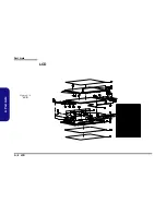
Страница 44: ...Part Lists A 6 LCD A Part Lists LCD 㾲䈷 㾲䈷 㾲䈷 㾲䈷 㾲䈷 㾲䈷 㾲䈷 㾲䈷 㦈㪾䇃 㾲䈷 褜㬘 㾲䈷 㾲䈷 㾲䈷 㾲䈷 㾲䈷 㾲䈷 㾲䈷 㾲䈷 㾲䈷 㾲䈷 㾲䈷 㾲䈷 㾲䈷 㾲䈷 㾲䈷 㾲䈷 㾲䈷 褜㬘 㾲䈷 褜㬘 㾲䈷 㕻㢲 㾲䈷 㾲䈷 㾲䈷 Figure A 4 LCD ...

Страница 45: ...Part Lists Mainboard A 7 A Part Lists Mainboard 㾲䈷 㾲䈷 㾲䈷 㾲䈷 㾲䈷 㾲䈷 㾲䈷 㾲䈷 㾲䈷 㾲䈷 㾲䈷 㾲䈷 㙲㗺 㾲䈷 㾲䈷 㾲䈷 㗮䓃㗱㥽 㾲䈷 㙲㗺 㾲䈷 㯵䀜 䧰㞡 㾲䈷 㾲䈷 㾲䈷 㮄䈠 㾲䈷 㾲䈷 㾲䈷 㾲䈷 㾲䈷 㾲䈷 㾲䈷 㾲䈷 㾲䈷 㾲䈷 㾲䈷 㾲䈷 㯵䀜 㾲䈷 㮄䈠 㾲䈷 㾲䈷 㾲䈷 Figure A 5 Mainboard ...

Страница 46: ...Part Lists A 8 Blu Ray Combo A Part Lists Blu Ray Combo 㾲䈷 㾲䈷 㾲䈷 㾲䈷 㕰㖑䜛 㾲䈷 Figure A 6 Blu Ray Combo ...

Страница 47: ...Part Lists DVD Super Multi A 9 A Part Lists DVD Super Multi 㾲䈷 㾲䈷 㖑䜛 㾲䈷 㖑䜛 㾲䈷 㾲䈷 㾲䈷 Figure A 7 DVD Super Multi ...

Страница 48: ...Part Lists A 10 A Part Lists ...

Страница 49: ...Click FP Board Page B 43 MCP79 PCI LPC Page B 10 Card Reader IEEE 1394 Page B 27 Logo LED Board Page B 44 MCP79 SATA USB Page B 11 MXM 3 0 Master Page B 28 Game Key Board Page B 45 MCP79 HDA Misc Page B 12 MXM 3 0 Slave Page B 29 TouchPad LED Board Page B 46 MCP79 Power Page B 13 MB to Small B d Connector A Page B 30 Front R Side LED Board Page B 47 MCP79 GND RMGT PWR PWRGD Page B 14 MB to Small B...

Страница 50: ...Schematic Diagrams B 2 System Block Diagram B Schematic Diagrams System Block Diagram Sheet 1 of 53 System Block Diagram ...

Страница 51: ...Schematic Diagrams PENRYN 1 2 B 3 B Schematic Diagrams PENRYN 1 2 Sheet 2 of 53 PENRYN 1 2 ...

Страница 52: ...Schematic Diagrams B 4 PENRYN3 2 2 B Schematic Diagrams PENRYN3 2 2 Sheet 3 of 53 PENRYN 2 2 ...

Страница 53: ...Schematic Diagrams MCP79 FSBI B 5 B Schematic Diagrams MCP79 FSBI Sheet 4 of 53 MCP79 FSB ...

Страница 54: ...Schematic Diagrams B 6 MCP79 MEM CTRL 1 B Schematic Diagrams MCP79 MEM CTRL 1 Sheet 5 of 53 MCP79 MEM CRTL 1 ...

Страница 55: ...Schematic Diagrams MCP79 MEM CTRL 2 B 7 B Schematic Diagrams MCP79 MEM CTRL 2 Sheet 6 of 53 MCP79 MEM CRTL 2 ...

Страница 56: ...Schematic Diagrams B 8 MCP79 PCI E B Schematic Diagrams MCP79 PCI E Sheet 7 of 53 MCP79 PCI E ...

Страница 57: ...Schematic Diagrams MCP79 LAN Panel B 9 B Schematic Diagrams MCP79 LAN Panel Sheet 8 of 53 MCP79 LAN Panel ...

Страница 58: ...Schematic Diagrams B 10 MCP79 PCI LPC B Schematic Diagrams MCP79 PCI LPC Sheet 9 of 53 MCP79 PCI LPC ...

Страница 59: ...Schematic Diagrams MCP79 SATA USB B 11 B Schematic Diagrams MCP79 SATA USB Sheet 10 of 53 MCP79 SATA USB ...

Страница 60: ...Schematic Diagrams B 12 MCP79 HDA Misc B Schematic Diagrams MCP79 HDA Misc Sheet 11 of 53 MCP79 HDA Misc ...

Страница 61: ...Schematic Diagrams MCP79 Power B 13 B Schematic Diagrams MCP79 Power Sheet 12 of 53 MCP79 Power ...

Страница 62: ...Schematic Diagrams B 14 MCP79 GND RMGT PWR PWRGD B Schematic Diagrams MCP79 GND RMGT PWR PWRGD Sheet 13 of 53 MCP79 GND RMGT PWR PWRGD ...

Страница 63: ...Schematic Diagrams DDR3 SO DIMM_0 B 15 B Schematic Diagrams DDR3 SO DIMM_0 Sheet 14 of 53 DDR3 SO DIMM_0 ...

Страница 64: ...Schematic Diagrams B 16 DDR SO DIMM_1 B Schematic Diagrams DDR SO DIMM_1 Sheet 15 of 53 DDR3 SO DIMM_1 ...

Страница 65: ...Schematic Diagrams Panel Inverter TPM B 17 B Schematic Diagrams Panel Inverter TPM Sheet 16 of 53 Panel Inverter TPM ...

Страница 66: ...Schematic Diagrams B 18 HDMI Fan Control B Schematic Diagrams HDMI Fan Control Sheet 17 of 53 HDMI Fan Control ...

Страница 67: ...Schematic Diagrams CRT DVI B 19 B Schematic Diagrams CRT DVI Sheet 18 of 53 CRT DVI ...

Страница 68: ...Schematic Diagrams B 20 ODD CCD BT USB 2 0 B Schematic Diagrams ODD CCD BT USB 2 0 Sheet 19 of 53 ODD CCD BT USB 2 0 ...

Страница 69: ...Schematic Diagrams KBC ITE IT8512 J B 21 B Schematic Diagrams KBC ITE IT8512 J Sheet 20 of 53 KBC ITE IT8512 J ...

Страница 70: ...Schematic Diagrams B 22 PHY RTL8211CL B Schematic Diagrams PHY RTL8211CL Sheet 21 of 53 PHY RTL8211CL ...

Страница 71: ...Schematic Diagrams Codec Subwoofer DMIC B 23 B Schematic Diagrams Codec Subwoofer DMIC Sheet 22 of 53 Codec Subwoofer DMIC ...

Страница 72: ...Schematic Diagrams B 24 Audio AMP B Schematic Diagrams Audio AMP Sheet 23 of 53 Audio AMP ...

Страница 73: ...Schematic Diagrams HDMI Switch B 25 B Schematic Diagrams HDMI Switch Sheet 24 of 53 HDMI Switch ...

Страница 74: ...Schematic Diagrams B 26 New Card Mini Card B Schematic Diagrams New Card Mini Card Sheet 25 of 53 New Card Mini Card ...

Страница 75: ...Schematic Diagrams Card Reader IEEE 1394 B 27 B Schematic Diagrams Card Reader IEEE 1394 Sheet 26 of 53 Card Reader IEEE1394 ...

Страница 76: ...Schematic Diagrams B 28 MXM 3 0 Master B Schematic Diagrams MXM 3 0 Master Sheet 27 of 53 MXM 3 0 Master ...

Страница 77: ...Schematic Diagrams MXM 3 0 Slave B 29 B Schematic Diagrams MXM 3 0 Slave Sheet 28 of 53 MXM 3 0 Slave ...

Страница 78: ...Schematic Diagrams B 30 MB to Small B d Connector A B Schematic Diagrams MB to Small B d Connector A Sheet 29 of 53 MB to Small B d Connector A ...

Страница 79: ...Schematic Diagrams MB to Small B d Connector B B 31 B Schematic Diagrams MB to Small B d Connector B Sheet 30 of 53 MB to Small B d Connector B ...

Страница 80: ...Schematic Diagrams B 32 Power System B Schematic Diagrams Power System Sheet 31 of 53 Power System ...

Страница 81: ...Schematic Diagrams Power VCore B 33 B Schematic Diagrams Power VCore Sheet 32 of 53 Power VCore ...

Страница 82: ...Schematic Diagrams B 34 PWR 1 05V Screw Hole B Schematic Diagrams PWR 1 05V Screw Hole Sheet 33 of 53 PWR 1 05V Screw Hole ...

Страница 83: ...Schematic Diagrams Power 1 5V 0 75V B 35 B Schematic Diagrams Power 1 5V 0 75V Sheet 34 of 53 Power 1 5V 0 75V ...

Страница 84: ...Schematic Diagrams B 36 Power 1 0VS B Schematic Diagrams Power 1 0VS Sheet 35 of 53 Power 1 0VS ...

Страница 85: ...Schematic Diagrams Power 3 3V 5V B 37 B Schematic Diagrams Power 3 3V 5V Sheet 36 of 53 Power 3 3V 5V ...

Страница 86: ...Schematic Diagrams B 38 Power Charger DC In B Schematic Diagrams Power Charger DC In Sheet 37 of 53 Power Charger DC In ...

Страница 87: ...Schematic Diagrams Single HDD Board B 39 B Schematic Diagrams Single HDD Board Sheet 38 of 53 Single HDD Board ...

Страница 88: ...Schematic Diagrams B 40 Dual HDD Board B Schematic Diagrams Dual HDD Board Sheet 39 of 53 Dual HDD Board ...

Страница 89: ...Schematic Diagrams Audio Board B 41 B Schematic Diagrams Audio Board Sheet 40 of 53 Audio Board ...

Страница 90: ...Schematic Diagrams B 42 Power Button Board B Schematic Diagrams Power Button Board Sheet 41 of 53 Power Button Board ...

Страница 91: ...Schematic Diagrams Click FP Board B 43 B Schematic Diagrams Click FP Board Sheet 42 of 53 Click FP Board ...

Страница 92: ...Schematic Diagrams B 44 Logo LED Board B Schematic Diagrams Logo LED Board Sheet 43 of 53 Logo LED Board ...

Страница 93: ...Schematic Diagrams Game Key Board B 45 B Schematic Diagrams Game Key Board Sheet 44 of 53 Game Key Board ...

Страница 94: ...Schematic Diagrams B 46 TouchPad LED Board B Schematic Diagrams TouchPad LED Board Sheet 45 of 53 TouchPad LED Board ...

Страница 95: ...Schematic Diagrams Front R Side LED Board B 47 B Schematic Diagrams Front R Side LED Board Sheet 46 of 53 Front R Side LED Board ...

Страница 96: ...Schematic Diagrams B 48 Front L Side LED Board B Schematic Diagrams Front L Side LED Board Sheet 47 of 53 Front L Side LED Board ...

Страница 97: ...Schematic Diagrams Back L Side LED Board B 49 B Schematic Diagrams Back L Side LED Board Sheet 48 of 53 Back L Side LED Board ...

Страница 98: ...Schematic Diagrams B 50 Touch Sensor Board A B Schematic Diagrams Touch Sensor Board A Sheet 49 of 53 Touch Sensor Board A ...

Страница 99: ...Schematic Diagrams Touch Sensor Board B B 51 B Schematic Diagrams Touch Sensor Board B Sheet 50 of 53 Touch Sensor Board B ...

Страница 100: ...oard Sheet 51 of 53 CIR Board KGND KGND KVDD5 KVDD5_CIR KGND KGND KVDD5 KGND KGND KCIR_RX KCIR_RX KC3 10U_10V_08 KH_O1 KH_O2 KC1 0 1U_16V_04 KR1 100_04 KH_O3 KC2 4 7U_10V_X5R_06 KJ_MB 88266 03001 1 2 3 KU1 IRM V038 TR1 P O G V GND1 GND2 O G V GND1 GND2 CIR BOARD ...

Страница 101: ...Schematic Diagrams Finger Board B 53 B Schematic Diagrams Finger Board Sheet 52 of 53 Finger Board ...

Страница 102: ...Schematic Diagrams B 54 PWR on SEQ Diagram B Schematic Diagrams PWR on SEQ Diagram Sheet 53 of 53 PWR on SEQ Diagram ...

Отзывы: