


Disassembly
2 - 11
2.Disassembly
3.
Remove the HDD support module
(
Figure 7b
).
4.
Grip the mylar cover and slide the hard disk in the direction of arrow
(
Figure 7b
).
5.
Lift the hard disk
out of the bay
(
Figure 7c
)
.
6.
Remove the screws
-
and adhesive mylar cover
from the hard disk
(
Figure 7d
)
.
7.
Reverse the process to install a new hard disk (do not forget to replace all the screws and cover).
6
3
4
6
5
6
7
8
6
9
6
5
3. HDD Support Module
5. HDD
9. Adhesive Mylar Co-
ver
•
2 Screws
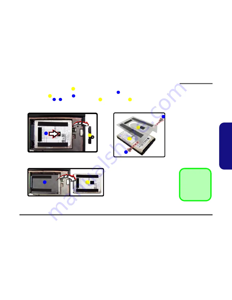
Figure 7
HDD Assembly
Removal (cont’d.)
b. Remove the HDD sup-
port module. Grip the
mylar cover and slide the
HDD in the direction of
the arrow.
c. Lift the HDD assembly
out of the bay.
d. Remove the screws and
adhesive cover.
4
b.
c.
6
d.
3
8
7
5
5
9
Содержание M1110Q
Страница 1: ......
Страница 2: ......
Страница 3: ...Preface I Preface Notebook Computer M1110Q M1110Q C Service Manual ...
Страница 24: ...Introduction 1 12 1 Introduction ...
Страница 38: ...Disassembly 2 14 2 Disassembly ...
Страница 41: ...Part Lists Top A 3 A Part Lists Top Figure A 1 Top Figure A 1 Top ...
Страница 42: ...Part Lists A 4 Bottom A Part Lists Bottom Figure A 2 Bottom ...
Страница 43: ...Part Lists LCD A 5 A Part Lists LCD 非耐落 Figure A 3 LCD ...
Страница 44: ...Part Lists A 6 A Part Lists ...
Страница 72: ...Schematic Diagrams B 28 Power Button Board B Schematic Diagrams ...


