1942207
V1.3
19 May 2022
Instruction Sheet Template - V1.3 – Updated 20/01/2022
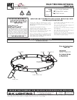
Installation:
The L10 Cleverfit LED Exit can be installed either Ceiling or Wall Mounted and can be mounted
perpendicular to a wall using the (optional) Cleverfit Cantilever Bracket. The fitting uses a “slide connect
bracket base” that is mounted and wired into position first. The main body can be installed once the base
is wired or later to avoid damage during the construction phase. Please follow the steps below to install
the Cleverfit Exit:
•
Disengage the slide connect bracket from the exit body. Position the base in the mounting position.
•
Using the bracket as a guide, mark 2 holes for mounting and one for mains access. Then install the
bracket using appropriate fixings (not supplied).
•
Connect the 240VAC supply to the mounting bracket.
•
Configure all the mounting parts and cable entry points as below (if required) and engage the body
into the slide connect bracket. Apply mains power and check that the Cleverfit Exit is operational.
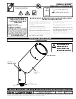
Dimensions:
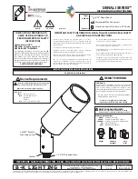
Changing Exit Legend Inserts:
The Cleverfit Exit uses Clevertronics patented “Tamper proof” Exit legend cover and comes complete with
spare legend inserts to enable straight on, left or right arrow as well as SS/DS combinations.
To change an Exit legend insert first remove the diffuser. The clear tamper proof cover is held in place by
3 locking tabs in the top inside area of the diffuser. Use a tool to disengage and push the locking tabs
through to release the cover and remove the insert, replacing it with the desired one. When double sided
is required remove the cardboard insert from the second side when adding decal.
To re-install the clear cover, first engage the 3 small lugs on the bottom of the cover into their respective
recesses in the diffuser. Once sure the lugs are located, and then the 2 side lugs, carefully push the 3
locking tabs back in, to complete the process.
Testing:
Once connected to the 240V mains supply, the unit must be allowed to charge the battery for at least 24
hours. Conduct the following tests:
•
For the first test, the emergency lamp must remain illuminated for at least 2 hours after
disconnection from the mains supply.
•
Subsequent tests require the unit to illuminate for at least 90 minutes. The results of all tests are
required to be recorded in a service logbook, which is to be kept on-site at all times. If the unit fails
to remain illuminated for the requisite time, remedial action must be taken to repair the situation
and once completed, the unit must pass a subsequent test. For more specific information, please
refer to the current edition of the AS 2293.3 Standard.
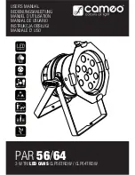
Cleverfit Maintenance:
Lamp Replacement:
•
Use only the lamp(s) recommended on the
label inside the Cleverfit.
•
To replace the lamp bar, remove the self-
tapping screws, disconnect the signal cable
and install the new lamp bar.
Battery Replacement:
•
Use only the battery recommended on the
label inside the Cleverfit and on this
instruction.
•
Remove the cable ties holding the battery,
un-plug the lead from the PCB and remove
the old battery.
•
Clip the new battery into the holder, route the
DC cable to the PCB and plug the new
battery into the PCB.
•
Secure the battery using suitable cable ties
Trouble Shooting:
Below are a list of common problems and their possible causes.
Fault: The Green LED Test Switch indicator is not illuminated.
Check: A.C. is connected and is turned on.
Battery is connected
Test Switch for damage.
Fault: Lamp does not illuminate in emergency mode.
Check: A.C. is connected.
Lamp is correctly inserted.
Battery is connected
Fault: Lamp illuminates in emergency mode, but only stays on for a short period.
Check: Battery has been allowed to charge for at least 24 hours.
Battery for damage.
Rated Emergency Lumen Output in accordance with AS2293.1, not applicable
for –TH (theatre) version (refer to spacing tables for installation positions):
Refer to the Technical Label for classification information.
Caution:
On many building sites, power circuits may be cut off in an uncontrolled and repetitive basis during
construction. As a result, any Exit & Emergency Units, on these circuits, will have their batteries
discharged or “cycled”. The battery in this fitting has been selected to give excellent long-life
performance in a controlled AS2293 testing environment. Excessive battery cycling will reduce through-
life performance and may lead to premature battery failure. Battery warranty claims, as a result of such
abuse, are specifically EXCLUDED from Clevertronics warranty terms.
Warranty:
For Product Warranty information and Terms and Conditions of Sales please refer to our website
http://clevertronics.com.au/terms-conditions-sale-australia-nz/