


Page 46
Model 21 -CET-8 Service Manual
Manual and Timed Modes
The SteamCraft 3.1 has two operating modes: manual and timed. The
TIMED/MANUAL rocker switch selects the operating mode. Pressing the
MANUAL end of the switch selects the manual operating mode. Pressing the
TIMED end of the switch selects the timed operating mode.
• Manual Mode provides continuous steaming. The operator starts and stops
steaming operations manually.
• Timed Mode provides timed control of steaming operations. The timer starts and
stops steaming operations.
Cooking procedures are slightly different for each mode. The diagram in Figure 3-7
illustrates which procedures are common to both modes and which are specific to
each mode.
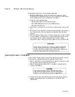
Main Power Switch
Usually the SteamCraft 3.1 main power switch is left ON. If the main power switch
was left in the OFF position, turn it ON as follows.
1. Check that the water supply valves are open.
2. If the control panel power is on, turn it off by pressing the OFF (bottom) end of
the ON/OFF switch.
3. The TIMED/MANUAL switch and timer settings are not important in this
procedure. The control panel circuits are not powered while the ON/OFF switch
is set to OFF.
4. Refer to the main power switch in Figure 3-8, and turn on electric power to the
SteamCraft 3.1. The steamer will immediately start a blowdown cycle. The
blowdown cycle lasts 3 minutes.
NOTE:
If it is necessary to stop the blowdown cycle before it is finished, turn
the ON/OFF switch to ON. (Refer to Power ON and Preheat.)
Figure 3-8. Main Power Switch
Power ON (Automatic Fill)
When the SteamCraft 3.1 is turned on, it automatically fills the steam generator with
water. Use this procedure at the beginning of a shift to prepare the steamer for
operation without starting steam generation. When ready to start steam cooking,
begin either the Timed or Manual Operating Procedure.
1. Check the control panel settings. If necessary, refer to the control panel summary
on page 44, and change the settings so:
• The ON/OFF switch is in the OFF (bottom) position.
• The TIMED/MANUAL switch is in the TIMED (top) position.
• The Timer dial points to 0.
2.
If the Timer is not zeroed (0), turn the dial counterclockwise until it points to 0.
Содержание steamcraft 21-CET-8
Страница 9: ......
Страница 53: ...Model 21 CET 8 Service Manual Page 45 Printed 12 90 ...
Страница 72: ...Model 21 CET 8 Service Manual Page 65 Figure 5 1 Block Diagram Key Pad Control Panel Printed 12 90 ...
Страница 104: ...Model 21 CET 8 Service Manual Page 97 Printed 12 90 ...
Страница 109: ...Figure 6 1 Major Component Groups Printed 12 90 ...
Страница 110: ...Page 104 21 CET 8 Service Manual Figure 6 2 Access Panel and External Components Printed 12 90 ...
Страница 112: ...Page 106 21 CET 8 Service Manual Figure 6 3 Steamer Compartment Group Printed 12 90 ...
Страница 114: ...Figure 6 4 Compartment Door And Hinge Assemblies Printed 12 90 ...
Страница 116: ...Page 110 21 CET 8 Service Manual Figure 6 5 Electronic Timer Control Panel Assembly Printed 12 90 ...
Страница 118: ...Page 112 21 CET 8 Service Manual Figure 6 6 Mechanical Timer Control Panel Assembly Printed 12 90 ...
Страница 120: ...Page 114 21 CET 8 Service Manual Figure 6 7 Electrical Components Assembly Printed 12 90 ...
Страница 122: ...Figure 6 8 Steam Generator Assembly Printed 12 90 ...
Страница 124: ...Figure 6 0 Heater Assembly Printed 12 90 ...
Страница 126: ...Page 120 21 CET 8 Service Manual Figure 6 1 OA Float Assembly Before Serial WC11379 901 01 Printed 12 90 ...
Страница 128: ...Page 122 21 CET 8 Service Manual Figure 6 10B Float Assembly After Serial WC11379 901 01 Printed 12 90 ...
Страница 130: ...Figure 6 11 Water Inlet System Printed 12 90 ...
Страница 132: ...Figure 6 12 Condenser And Drainage Systems Printed 12 90 ...
Страница 134: ...Figure 6 13 Equipment Stand Printed 12 90 ...
Страница 136: ...Figure 6 14 SteamCraft 3 1 Wiring Diagram Electronic Time Printed 12 90 ...
Страница 137: ...Figure 6 15 SteamCraft 3 1 Schematic Diagram Electronic Timer Printed 12 90 ...
Страница 138: ...Figure 6 16 SteamCraft 3 1 Wiring Diagram Mechanical Timer Printed 12 90 ...
Страница 139: ...Figure 6 17 SteamCraft 3 1 Schematic Diagram Mechanical Timer Printed 12 90 ...


