background image

Apex Tool Group

P2055MA | 2019-09

13

EN

5

Initial operation

1. Position the Spindle components together via flat 

toothed interfaces, see Service manual. 
-

Turn size 1 in 15° increments.

-

Turn sizes 4 to 2 in 10° increments.

2. Connect all components.
3. Establish a grounding connection on the mounting 

plate to ensure the function.

4. However, protective earthing of moving parts has to be 

made acc. to EN 60204-1.

5. Close all plug connectors and lock.

The red ring around the outer diameter of plug connec-
tors with a slide lock should not be visible.

6. Connect the mains cable to the controller.

7. Preset the ARCNET address on each Tightening Mod-

ule STM(…) 

via BCD-code switch

:

-

Upper switch for tens digit (

0

0-

9

0)

-

Bottom switch for ones digit (0

0

-0

9

)

-

Admissible settings 01 to 32.

-

The address adjustment can be checked upon 
power-up or reset at the two-digit 7-segment dis-
play.

8. Close the protective devices (e.g. safety grilles).
9. Switch on the machine control unit (PLC/SPS).
10. Switch on the controller. 
11. If there are no faults pending after switching on the 

unit, the "Ready" LED on the tightening module lights 
up green. Otherwise see System Handbook for Trou-
ble Shooting.

12. Enter the parameters for the torque / angle setting via 

the controller. 
The controller is programmed prior to initial operation 
by Apex Tool Group. When switching on the controller 
for the first time, the parameters for controlling the fas-
tening sequences must be read in via the keyboard or 
via a valid parameter file. Process programming of the 
controller see Programming Manual.

Danger

High leakage current – 

Fatal electric shock could occur.

Establish a grounding connection (PE) 
to the controller before taking into op-
eration!

Caution

Risk of tripping or falling over.

Loose cables on the ground.

Lay all connected cables safely.

Always switch off the controller before 
making adjustments.

Each address can be used only once 
in the system. Otherwise an error is 
triggered on the controller.

Содержание BB P2055MA

Страница 1: ...For additional product information visit our website at www ClecoTools com Assembly Instructions P2055MA 2019 09 Fixtured Spindle Series BB ...

Страница 2: ...dable language or transmitted on electronic mechanical optical or other media without the express permission of the Apex Tool Group Disclaimer Apex Tool Group reserves the right to modify supplement or improve this document or the product without prior notice Trademark Cleco is a registered trademark of Apex Brands Inc Apex Tool Group GmbH Industriestraße 1 73463 Westhausen Germany ...

Страница 3: ... Operator Training 5 2 5 Personal Protective Equipment 6 2 6 Warnings and Notes 6 2 7 Symbols on the Product 6 2 8 Principles of safe working 6 3 Transport 7 4 Installation 8 4 1 Drilling templates in mounting plate 8 4 2 Attaching the Spindle to the mounting plate 12 5 Initial operation 13 6 Ambient conditions 14 7 Noise 14 8 Maintenance 14 9 Disposal 14 ...

Страница 4: ...4 P2055MA 2019 09 Apex Tool Group EN ...

Страница 5: ...ponent to Sales Service Centers Always remove the complete Spindle from a unit 2 3 Predictable Misuse Do not use the Spindle In potentially explosive areas In damp locations or outdoors In non industrial applications eg residential area 2 4 Operator Training The fastening system may only be put into operation adjusted tested maintained and serviced by quali fied1 and trained personnel Personnel mu...

Страница 6: ...ore making throughput resistance and short circuit measurements Do not attempt to repair possible faults on the fasten ing system by yourself if you do not have the required knowledge Inform the local repair center or your Sales Service Centers Hazards from ejected parts Components of the spindle may rotate come loose and cause injury Avoid speed increases of over 328 ft s 100 m s on all axes Obse...

Страница 7: ...ected NOK tightening could have life threatening consequences Recalibration or capability analysis is essential fol lowing incorrect use crash mechanical overload For category A tightenings VDI 2862 which are criti cal for safety activate a redundancy measurement e g current redundancy Introduce regular monitoring of measuring equipment on the machines Do not use defective systems If in doubt cont...

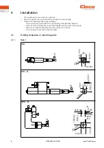
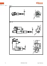
Страница 8: ...he following points during installation the service panel is accessible for one off setting of the ARCNET address warm air must not be produced under the Spindle also from other components there are no objects obstructing the air flow at the top or bottom the housing is not exposed to direct sunlight 4 1 Drilling templates in mounting plate 4 1 1 Size 1 1ZB 1VK B 1WK B 0 ...

Страница 9: ...Apex Tool Group P2055MA 2019 09 9 EN 4 1 2 Size 2 2ZB 2VK B 2WK B 0 ...

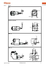
Страница 10: ...10 P2055MA 2019 09 Apex Tool Group EN 4 1 3 Size 3 3ZB 3VK B 3WK B 0 ...

Страница 11: ...Apex Tool Group P2055MA 2019 09 11 EN 4 1 4 Size 4 4ZA 4Z1250A 4Z1600A 4VK B 4WK B 0 ...

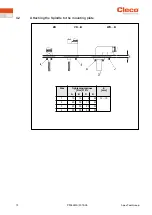
Страница 12: ...12 P2055MA 2019 09 Apex Tool Group EN 4 2 Attaching the Spindle to the mounting plate Size Tightening torques Nm 10 E mm A B C D 1 10 10 6 25 12 15 2 25 50 10 25 3 25 50 25 50 4 50 50 85 85 ZB VK B WK B ...

Страница 13: ... protective devices e g safety grilles 9 Switch on the machine control unit PLC SPS 10 Switch on the controller 11 If there are no faults pending after switching on the unit the Ready LED on the tightening module lights up green Otherwise see System Handbook for Trou ble Shooting 12 Enter the parameters for the torque angle setting via the controller The controller is programmed prior to initial o...

Страница 14: ...ains components that can be reused as well as components that require special disposal Separate the components and dispose of them by segregating them clearly Catch auxiliary materials oils greases when drained and dispose of them properly Separate the components of the packing and dispose of them by segregating them clearly Follow the locally applicable regulations Enclosure type according to DIN...

Страница 15: ......
Страница 16: ...ex Tool Group GmbH C O Spline Gauges Piccadilly Tamworth Staffordshire B78 2ER United Kingdom Phone 44 1827 8727 71 Fax 44 1827 8741 28 FRANCE Apex Tool Group SAS 25 Avenue Maurice Chevalier ZI 77330 Ozoir La Ferrière France Phone 33 1 64 43 22 00 Fax 33 1 64 43 17 17 GERMANY Apex Tool Group GmbH Industriestraße 1 73463 Westhausen Germany Phone 49 0 73 63 81 0 Fax 49 0 73 63 81 222 GHUNGARY Apex T...

Отзывы: