background image

Page 55

PL92-5013EN

10/06/2017

EN

Description

1

634712PT

1

Spindle Thrust Cap

2

634747PT

1

2 Ball Bearing

3

634714PT

1

Feed Gear Spacer

(#) Quantity

(X) Recommended Spare Parts (quantity shown based on 1-5 tools in operation)

Illustration 32: 642488PT Spindle Thrust Cap Kit - MITIS (No Cam)

Ref

Number

#

X

3 Roller Cam

5 Roller Cam

Cam Height (mm)

642661PT-10

642686PT-10

0.10

642661PT-15

642686PT-15

0.15

642661PT-20

642686PT-20

0.20

642661PT-25

642686PT-25

0.25

642661PT-30

642686PT-30

0.30

642661PT-35

642686PT-35

0.35

Illustration 33: MITIS Cam Kits

Service Parts

Содержание A24T

Страница 1: ...For additional product information visit our website at http www ClecoTools com Inline Right Angle Service and Parts Manual PL92 5013EN 10 06 2017 A2 Series Advanced Drilling ...

Страница 2: ... 00 22 Illustration 12 Single Stage Gearing Gear Ratios 3 67 4 00 4 75 6 00 24 Illustration 13 Double Stage Gearing Gear Ratios 9 00 13 50 6 00 19 00 26 Illustration 14 Double Stage Gearing Gear Ratios 22 56 24 00 28 50 36 00 28 Illustration 15 Right Angle Gear Head 30 Illustration 16 Inine Gear Head 32 Illustration 17 Primary Gear Head 34 Illustration 18 Secondary Gear Head 36 Illustration 19 634...

Страница 3: ...Nut 64 Illustration 45 23500046 Microstop 64 Illustration 46 Accesssory Kits 66 Illustration 47 642579PT Pistol Handle Kit 68 Illustration 48 642600PT Logic Manifold Kit 68 Illustration 49 642593PT Lubricator Kit 70 Illustration 50 642591PT Counter Kit 70 Illustration 51 Template Foot Kits 72 Illustration 52 Template Foot 642176PT 642358PT with Lead Screw Kit 74 Illustration 53 Template Foot 64217...

Страница 4: ...es the type of danger Indicates a potentially hazardous situation for personal health and safety If this warning is not observed death or serious injury may occur Indicates a potentially hazardous situation which if not avoided may result in minor or moderate injury or property and environmental damage GENERAL NOTE identifies information that may include application tips but no hazardous situation...

Страница 5: ...6 feet Compressed air quality according to ISO 8573 1 2010 2 4 3 Recommended oil rotary vane motors only Airlube 533485 1 US Gallon 3L Airlube 540397 1 US Quart 0 9L Adjust the inline lubricator to dispense 2 drops of oil per minute at nominal flow Recommended grease gear head and planetary Accrolube High Efficiency Grease with PTFE manufactured by Accro Seal Any deviation of these instructions co...

Страница 6: ... in output or increased maintenance and may cancel the manufacturer s warranty Never lubricate the tool with flammable or volatile liquid gazoil aircraft fuel etc Disconnect the air supply before performing any maintenance on this equipment Daily Visual inspection of air supply hose and connections If lubrication is used check the oil tank level and operation Inspect all external tool components I...

Страница 7: ...mm rev A2 Turbine Series Base Tool Options Base Weight Feeds Base Tool Standard Option Code Noise Configuration Code Configuration Rated Speeds 0 20 Tool thrust 400 lbs at 90psi 6 3bar dynamic air supply lbs kg A24V 5 5 2 5 82dBA Right Angle Vane M Internal Mitis 5 200 12 000 3 00 1 0 001 0 025 A26V 5 3 2 4 82dBA In Line Vane F3 1 5 times per rev 4 500 10 500 3 00 1 0 002 0 050 F5 2 5 times per re...

Страница 8: ...chips debris removed Visually Inspect air supply hose all pneumatic connections Inspect airline filter regulator and lubricator for proper lubrication Check Air Supply Pressure 90psi dynamic Check spindle stop nuts are securely mounted Check all guards are fitted Check the tool for excessive vibration unusual noise Visual inspect all external components Especially inder if fitted for wear Check To...

Страница 9: ... 333 0 002 0 05 1 25 4 667 0 003 0 08 1 25 4 1 000 0 004 0 10 1 25 4 1 333 0 005 0 13 1 25 4 1 667 0 006 0 15 1 25 4 2 000 0 007 0 18 1 25 4 2 333 0 008 0 20 1 25 4 2 667 0 009 0 23 1 25 4 3 000 0 010 0 25 1 25 4 3 333 Actual Stroke Stroke Basis S MITIS Service Intervals x Recommended Service Intervals C Feed Rate Stroke Basis S To calculate a User Specific Service interval based on actual stroke ...

Страница 10: ... PL92 5013EN 10 06 2017 4 Service Parts Service Parts Gear Gead Illustration 1 A2 Components Power Unit Cover or Accessory Mounting Gear Gead Power Unit Cover or Accessory Mounting A24T Right Angle A26T Inline ...

Страница 11: ...58PT Double Stage 13 50 Ratio 642510PT 642659PT 6 642459PT Double Stage 16 00 Ratio 642510PT 642659PT 7 642642PT Double Stage 19 00 Ratio 642510PT 642659PT 8 642460PT Double Stage 22 56 Ratio 642510PT 642659PT 9 642643PT Double Stage 24 00 Ratio 642510PT 642659PT 10 642644PT Double Stage 28 50 Ratio 642510PT 642659PT 11 642461PT Double Stage 36 00 Ratio 642510PT 642659PT 12 642670PT Double Stage 9...

Страница 12: ...Rotary Vane Motor Module Refer to Illustration 8 2 Refer to Illustration 5 7 Refer to Illustration 9 6 1 3 4 5 Shim governor by inserting required shim combination above the governor spring to adjust motor rpm within 10 of target rpm 8 9 Refer to Illustration 10 Note orientation of motor Exhaust ports oriented to housing exhaust ports ...

Страница 13: ...lustration 4 642687PT X Rotary Vane Motor Module Ref Number X Table 4A Single Shim Part Number Single Shim Stack mm Shim Pack Height mm 635229PT 1 0 2 0 2 635229PT 2 0 3 0 3 635229PT 1 635229PT 1 0 2 0 2 0 4 635229PT 2 635229PT 1 0 3 0 2 0 5 635229PT 2 635229PT 2 0 3 0 3 0 6 635229PT 3 635229PT 1 0 5 0 2 0 7 635229PT 3 635229PT 2 0 5 0 3 0 8 635229PT 3 635229PT 1 635229PT 1 0 5 0 2 0 2 0 9 635229P...

Страница 14: ...3PT Safety Valve Assembly 3 Refer to Illustration 6 30 in lbs The Safety Valve assembly is under spring load remove carefully The correct length screw must be used to allow spring tension release without the screws becoming detached from the motor housing Service Parts ...

Страница 15: ...65mm 2 542940 42 1 Socket Head Cap Screw M4 x 35mm 3 1 Safety Body Assembly Refer to Illustration 6 4 634587PT 1 1 Compression Spring Quantity X Recommended Spare Parts quantity shown based on 1 5 tools in operation Illustration 5 642513PT Safety Valve Assembly Ref Number X Service Parts ...

Страница 16: ... 635045PT Safety Body Assembly Refer to Illustration 7 25 in lbs Loctite 243 24 9 17 7 2 3 4 5 6 5 8 10 12 13 14 10 11 11 11 19 20 21 23 22 1 2 3 2 2 4 in lbs 32 in lbs 17 in lbs Tighten unitl flush with face Loctite 243 Tighten unitl flush with face Loctite 243 Service Parts 30 in lbs 10 18 15 2 2 2 2 2 2 ...

Страница 17: ...6 94234140 1 Socket Head Cap Screw M3 x 8mm 17 91815677 1 3 O Ring 18 90225691PT 1 Safety Valve Cap 19 531226 1 Poppet Valve 20 634645PT 1 3 Compression Spring 21 642384PT 1 Start Button 22 90255216 1 Plug Assemble flush to surface 23 93800005 1 3 Screen 24 90810863PT 1 Inlet Adapter Quantity X Recommended Spare Parts quantity shown based on 1 5 tools in operation Illustration 6 642513PT Safety Bo...

Страница 18: ...stration 9 642689PT Vane Motor Assembly 5 1 6 Refer to Illustration 4 6 9 8 Service Parts 5 3 3 6 4 7 Assembly Note Turbine covers must be installed after the turbine motor assembly has been installed in the housinng Note the orientation of the turbine covers when installed 6 5 6 7 4 2 2 3 ...

Страница 19: ...s quantity shown based on 1 5 tools in operation Illustration 8 642510PT Turbine Motor Assembly Ref Number X EN Description 1 635244PT 1 Governor Valve 2 635243PT 2 Governor Weight 3 635242PT 1 Governor Body 4 207992PT 1 Rear End Plate 5 207997PT 1 Rotor 6 207988PT 4 12 Rotor Blade 7 635205PT 1 3 Rotor Key 8 207995PT 1 Cylinder Includes Ref 9 9 208021PT 1 Front End Plate Quantity X Recommended Spa...

Страница 20: ...Page 20 PL92 5013EN 10 06 2017 1 Illustration 10 642690PT Vane Muffler Assembly 1 Service Parts 2 4 5 6 1 3 ...

Страница 21: ...1 Muffler Housing 3 867745 1 3 O Ring Muffler Housing 4 635207PT 1 2 Muffler Diffuser 5 635208PT 1 2 Muffler Pad 6 635209PT 1 2 Muffler Element Quantity X Recommended Spare Parts quantity shown based on 1 5 tools in operation Illustration 10 642690PT Vane Muffler Assembly Ref Number X Service Parts ...

Страница 22: ...Page 22 PL92 5013EN 10 06 2017 11 9 9 Service Parts 3 1 5 6 8 11 4 7 10 1 2 9 9 9 9 Illustration 11 642669PT Single Stage Gearing Gear Ratio 3 00 ...

Страница 23: ...ar Cage 5 642666PT 3 6 Planetary Gear 11T 6 635117PT 3 6 Planetary Gear Pin 7 634765PT 1 Ring Gear 8 635116PT 1 Extension Pinion 9 91815042 15 45 O Ring 10 864964 1 1 Grease Fitting 11 542940 60 2 2 Socket Head Cap Screw M5 x 30mm Quantity X Recommended Spare Parts quantity shown based on 1 5 tools in operation T Teeth Illustration 11 642669PT Single Stage Gearing Gear Ratio 3 00 Ref Number X Serv...

Страница 24: ...Page 24 PL92 5013EN 10 06 2017 Page 24 Service Parts 12 10 10 3 1 5 7 9 12 4 8 11 1 2 10 10 10 10 6 Illustration 12 Single Stage Gearing Gear Ratios 3 67 4 00 4 75 6 00 ...

Страница 25: ...Fitting 12 542940 60 2 2 Socket Head Cap Screw M5 x 30mm Quantity X Recommended Spare Parts quantity shown based on 1 5 tools in operation Illustration 12 Single Stage Gearing Ref Number X Table 12 642457PT 642456PT 642455PT 642454PT Gear Ratio 3 67 4 00 4 75 6 00 Gear Cage Assembly 1 642648PT 1 642649PT 1 642650PT 1 642651PT 4 Gear Cage 1 207936PT 1 207934PT 1 634677PT 1 634777PT 5 Planetary Gear...

Страница 26: ...Page 26 PL92 5013EN 10 06 2017 Service Parts 16 14 3 1 9 11 13 16 8 12 15 1 2 14 14 14 14 10 Illustration 13 Double Stage Gearing Gear Ratios 9 00 13 50 16 00 19 00 5 7 6 4 ...

Страница 27: ...n Illustration 13 Double Stage Gearing Gear Ratios 9 00 13 50 16 00 19 00 Ref Number X Table 13 642670PT 642458PT 642459PT 642642PT Gear Ratio 9 00 13 50 16 00 19 00 Lower Gear Cage Assembly 1 642667PT 1 642648PT 1 642649PT 1 642649PT 4 Lower Planetary Gear Cage 1 635114PT 1 207936PT 1 207934PT 1 207934PT 5 Lower Planetary Gear 3 642666PT 11T 3 207939PT 14T 3 207932PT 14T 3 207932PT 14T 6 Lower Pl...

Страница 28: ...Page 28 PL92 5013EN 10 06 2017 Service Parts 16 14 3 1 9 11 13 16 8 12 15 1 2 14 14 14 14 10 Illustration 14 Double Stage Gearing Gear Ratios 22 56 24 00 28 50 36 00 5 7 6 4 ...

Страница 29: ...1 1 Grease Fitting 16 542940 54 2 2 Socket Head Cap Screw M5 x 45mm Quantity X Recommended Spare Parts quantity shown based on 1 5 tools in operation Illustration 14 Double Stage Gearing Gear Ratios 22 56 24 00 28 50 36 00 Ref Number X Table 14 642460PT 642643PT 642644PT 642461PT Gear Ratio 22 56 24 00 28 50 36 00 Lower Gear Cage Assembly 1 642650PT 1 642649PT 1 642650PT 1 642651PT 4 Lower Planeta...

Страница 30: ...Page 30 PL92 5013EN 10 06 2017 Illustration 15 Right Angle Gear Head Refer to Illustration 18 10 8 7 Refer to Illustration 17 2 1 13 Refer to Illustration 29 11 9 Service Parts 12 3 4 5 5 6 14 ...

Страница 31: ...010 5 634753PT 2 4 Ball Bearing 6 634704PT 1 Bearing Clamp Nut 7 634698PT 1 Bevel Gear Shaft 8 634703PT 1 Bevel Gear 9 642647PT 1 Shim Kit Includes the following shims 635086PT 001 1 Shim 001 635086PT 003 1 Shim 003 635086PT 005 1 Shim 005 635086PT 007 1 Shim 007 635086PT 009 1 Shim 009 635086PT 010 1 Shim 010 10 634705PT 1 Drive Pinion Gear 11 634819PT 1 3 Shear Pin 12 634557PT 1 2 Ball Bearing 1...

Страница 32: ...Page 32 PL92 5013EN 10 06 2017 Service Parts Illustration 16 Inline Gear Head Refer to Illustration 18 5 4 3 Refer to Illustration 17 1 8 6 7 2 Refer to Illustration 29 9 ...

Страница 33: ...ration 29 3 634798PT 1 2 Wear Bushing 4 634699PT 1 Inline Drift Shaft 5 634705PT 1 Drive Pinion Gear 6 634819PT 1 3 Shear Pin 7 634557PT 1 2 Ball Bearing 8 Illustration 18 1 Secondary Gear Head 9 634339PT 2 Dowel Pin Quantity X Recommended Spare Parts quantity shown based on 1 5 tools in operation Illustration 16 Inline Gear Head Ref Number X ...

Страница 34: ... 06 2017 Service Parts Illustration 17 Primary Gear Head Refer to Illustration 34 3 1 2 Refer to Illustration 30 30 in lbs 3 3 3 3 4 7 10 9 8 Refer to Illustration 35 6 Refer to Illustration 22 Refer to Illustration 23 5 11 ...

Страница 35: ...st Pack Kit High Speed Illustration 31 642488PT 1 Spindle Thrust Pack Kit MITIS Illustration 32 5 642470PT 1 Primary Housing Illustration 23 6 Illustration 22 Valve Assemblies 7 634752PT 1 2 Needle Bearing 8 642490PT 1 Differential Shaft Support Illustration 35 9 634811PT 1 3 O Ring 10 634700PT 1 Clutch Cup 11 634813PT 2 2 Clutch Cup Pin Quantity X Recommended Spare Parts quantity shown based on 1...

Страница 36: ...r to Illustrations 19 20 21 Refer to Illustration 36 30 in lbs 1 12 8 Refer to Illustration 25 26 27 Refer to Illustration 24 9 10 11 13 2 3 4 17 23 14 16 15 22 21 21 20 19 19 18 5 6 7 19 19 24 20 in lbs Loctite 243 30 in lbs 20 in lbs 20 in lbs 20 in lbs 20 in lbs Flush 26 28 29 25 27 ...

Страница 37: ...ng 10 634751PT 1 2 Ball Bearing Double Row 11 634708PT 1 Differential Feed Gear 12 634743PT 1 3 Differential Shaft Nut 13 634800PT 1 3 Retaining Ring 14 634706PT 1 Intermediate Drive Gear 15 634750PT 1 2 Ball Bearing 16 634801PT 1 2 Retaining Ring 17 634958PT 1 Bearing Spacer 18 642569PT 1 Differential Piston Housing Assembly Illustration 36 19 94234150 4 Socket Head Cap Screw M3 x 12mm 20 634695P...

Страница 38: ... 38 PL92 5013EN 10 06 2017 Service Parts Illustration 19 634709PT XX Spindle Feed Gear 1 Illustration 20 634787PT XX Spindle Feed Gear High Speed 1 Illustration 21 642486PT XX Spindle Feed Gear MITIS 1 2 3 ...

Страница 39: ...r 0 004 in rev 634787PT 60 1 Spindle Feed Gear Feed Rate ipr 0 006 in rev 634787PT 70 1 Spindle Feed Gear Feed Rate ipr 0 007 in rev 634787PT 80 1 Spindle Feed Gear Feed Rate ipr 0 008 in rev 634787PT 100 1 Spindle Feed Gear Feed Rate ipr 0 010 in rev Quantity X Recommended Spare Parts quantity shown based on 1 5 tools in operation Illustration 20 634787PT XX Spindle Feed Gear High Speed Ref Numbe...

Страница 40: ...Page 40 PL92 5013EN 10 06 2017 Service Parts Illustration 22 Gear Head Valve Assemblies 8 6 5 2 10 12 9 11 4 3 1 5 7 13 13 13 14 ...

Страница 41: ...6PT 1 3 O Ring 1mm x 2 5mm 7 634809PT 1 3 O Ring 0 04 x 0 07 8 634950PT 1 3 Compression Spring 9 634803PT 1 1 Retaining Ring 10 634720PT 1 Valve Plug 11 91815104 1 3 O Ring 1mm x 4 5mm 12 642473PT 1 JAVO 3C Valve Assembly includes Ref 13 14 13 91815104 3 9 O Ring 1mm x 4 5mm 14 634809PT 1 3 O Ring 0 04 x 0 07 Quantity X Recommended Spare Parts quantity shown based on 1 5 tools in operation Illustr...

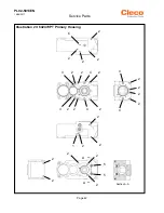
Страница 42: ...Page 42 PL92 5013EN 10 06 2017 Section A A Illustration 23 642470PT Primary Housing 2 2 6 2 2 2 4 2 A A 2 2 2 Service Parts 3 2 2 2 4 3 2 2 4 4 2 1 2 2 2 2 2 2 2 5 5 ...

Страница 43: ...crew M3 x 3mm 3 634326PT 2 Heli Coil M3 x 6mm 4 634327PT 4 Heli Coil M5 x 7 5mm 5 634608PT 2 Heli Coil M4 x 4mm 6 634829PT 1 Orifice Screw M3 x 4mm Quantity X Recommended Spare Parts quantity shown based on 1 5 tools in operation Illustration 23 642470PT Primary Housing Ref Number X Service Parts ...

Страница 44: ...tion 24 642471PT Secondary Housing 3 1 1 A A Service Parts 2 1 1 B B Section B B Apply Loctite 290 to the underside of the bearing spacer Assembly Notes Install set screws just below flush of face and bottom of counterbores Do not bottom out set screws ...

Страница 45: ...ription 1 634323PT 4 Set Screw M3 x 3mm 2 634805PT 1 Bushing 3 634958PT 1 Bearing Spacer Quantity X Recommended Spare Parts quantity shown based on 1 5 tools in operation Illustration 24 642471PT Secondary Housing Ref Number X Service Parts ...

Страница 46: ...N 10 06 2017 Service Parts Illustration 25 634393PT Standard Nose Adapter 1 Illustration 26 642323PT Manual Indexer Nose Adapter 1 Illustration 27 642585PT Lever Style Indexer Nose Adapter 1 3 2 Refer to Illustration 28 ...

Страница 47: ...ose Adapter 1 20 LH Thread includes Ref 1 3 1 625567 1 Clamp Nut 2 634409PT 1 Nose Adapter 3 634425PT 1 Tool Adapter Quantity X Recommended Spare Parts quantity shown based on 1 5 tools in operation Illustration 26 642323PT Manual Nose Adapter Ref Number X EN Description 1 642585PT 1 Lever Nose Adapter 1 20 LH Thread Illustration 28 Quantity X Recommended Spare Parts quantity shown based on 1 5 to...

Страница 48: ...642585PT Indexer Assembly 4 Ref A A Service Parts B B Section B B Assembly Notes Ref 3 Apply Chevron Black Pearl grease NLGI 2 to the inner and outer ball race Ref 6 Peen top and bottom of dowel pin hole to keep pin from falling out 8 12 11 5 1 8 3 2 4 6 9 10 7 ...

Страница 49: ...ring Rest Pad 6 90010015 1 Pin 7 634977PT 1 Dowel Pin 3mm x 22mm 8 634221PT 2 Socket Head Cap Srew M3 9 632626 1 Fulcrum Screw 10 634976PT 1 Spacer 11 634975PT 1 3 Torsion Spring Left Hand 12 634974PT 1 3 Torsion Spring Right Hand Quantity X Recommended Spare Parts quantity shown based on 1 5 tools in operation Illustration 28 642585PT Indexer Assembly Ref Number X Service Parts ...

Страница 50: ...ration 29 642478PT Gear Head Cover Assembly Service Parts Assembly Note Apply O Ring lubricant to O Rings during assembly 4 1 5 5 5 5 5 5 5 Assembly Note Install set screws just below flush of face and bottom of counterbores 4 4 2 2 3 3 5 ...

Страница 51: ...0 51 2 Socket Head Cap Screw M5 x 12mm 3 634323PT 2 Set Screw M3 x 3mm 4 634534PT 3 Set Screw M5 x 4mm 5 91815042 8 24 O Ring Quantity X Recommended Spare Parts quantity shown based on 1 5 tools in operation Illustration 29 642478PT Gear Head Cover Assembly Ref Number X Service Parts ...

Страница 52: ...487PT Spindle Thrust Cap Kit Standard Illustration 31 642641PT Spindle Thrust Cap Kit High Speed 1 2 3 2 4 1 2 Service Parts Assembly Note Pack thrust bearing with Accrolube Assembly Note Assemble spacer as shown Assembly Note Assemble spacer as shown ...

Страница 53: ... Recommended Spare Parts quantity shown based on 1 5 tools in operation Illustration 30 642487PT Spindle Thrust Cap Kit Standard Ref Number X EN Description 1 634786PT 1 Spindle Thrust Cap 2 635072PT 1 2 Ball Bearing Quantity X Recommended Spare Parts quantity shown based on 1 5 tools in operation Illustration 31 642641PT Spindle Thrust Cap Kit High Speed Ref Number X Service Parts ...

Страница 54: ...age 54 PL92 5013EN 10 06 2017 Illustration 32 642488PT Spindle Thrust Cap Kit MITIS No Cam Illustration 33 MITIS Cam Kits Service Parts 1 2 3 Assembly Note Assemble spacer as shown 3 Roller Cam Kit shown ...

Страница 55: ...ntity shown based on 1 5 tools in operation Illustration 32 642488PT Spindle Thrust Cap Kit MITIS No Cam Ref Number X 3 Roller Cam 5 Roller Cam Cam Height mm 642661PT 10 642686PT 10 0 10 642661PT 15 642686PT 15 0 15 642661PT 20 642686PT 20 0 20 642661PT 25 642686PT 25 0 25 642661PT 30 642686PT 30 0 30 642661PT 35 642686PT 35 0 35 Illustration 33 MITIS Cam Kits Service Parts ...

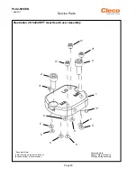
Страница 56: ...013EN 10 06 2017 Service Parts Illustration 34 642564PT Thrust Pack Cap Assembly Illustration 35 642490PT Differential Shaft Support Assembly 1 2 3 2 4 Assembly Note Pack thrust bearing with Accrolube 1 2 2 3 3 4 5 6 ...

Страница 57: ...ation Illustration 34 642564PT Thrust Pack Cap Assembly Ref Number X EN Description 1 634689PT 1 Differential Shaft Support 2 634357PT 2 2 Button Head Screw M3 x 6mm 3 634824PT 2 2 Button Head Screw M2 5 x 10mm 4 635071PT 1 Differential Cover 5 634806PT 1 Bushing 6 634790PT 1 Spring Adjustment Nut Quantity X Recommended Spare Parts quantity shown based on 1 5 tools in operation Illustration 35 642...

Страница 58: ...lustration 36 642569PT Differential Piston Housing Assembly 1 19 19 Service Parts Section A A A A B B Section B B 4 4 5 6 11 12 19 19 19 14 13 15 17 16 16 18 2 3 6 in lbs Loctite 243 6 in lbs Loctite 243 50 in lbs Loctite 243 7 8 9 10 ...

Страница 59: ...lve includes Ref 7 10 7 634891PT 1 JAV 2C Rod 8 634809PT 1 3 O Ring 9 634890PT 1 JAV 2C 3C Housing 10 634894PT 1 2 Spring Pin 11 634895PT 1 3 O Ring 12 634915PT 1 Differential Piston Housing 13 634758PT 1 Shutoff Guide 14 642476PT 1 JAV 3C Valve includes Ref 11 13 15 634396PT 1 3 O Ring 1mm x 2 5mm 16 91815104 2 6 O Ring 1mm x 4 5mm 17 634809PT 1 3 O Ring 0 40 x 0 070 18 634951PT 1 3 Compression S...

Страница 60: ...90277111 6 9 175 90277617PT 8 1 205 90277233 7 7 195 90277071 7 7 195 90277112 7 3 185 90277689PT 8 5 215 90277236 8 5 215 90277238 8 5 215 90277235 7 7 195 90277692PT 9 3 235 90277261 10 0 255 90277240 9 3 235 90277269 8 5 215 90277693PT 10 0 255 90277242 10 0 255 90277286 9 3 235 90277265 14 0 355 90277276 10 0 255 90277245 11 6 295 90277660 10 8 275 Note E200 Collet Clamp and other Straight Sha...

Страница 61: ...mended Spare Parts quantity shown based on 1 5 tools in operation Illustration 39 Slotted Spindle Guard Ref Number X in mm in mm 624328 2 00 50 8 624334 8 00 203 2 624329 3 00 76 2 624335 9 00 228 6 624330 4 00 101 6 624336 10 00 254 0 624331 5 00 127 0 624337 11 00 279 4 624332 6 00 152 4 634125PT 14 00 355 6 624333 7 00 177 8 624338 19 00 482 6 Table 39 Slotted Spindle Guard Part No Length Part ...

Страница 62: ...27 0 Aluminum 624342S 5 000 127 0 Steel 624096 6 000 152 4 Aluminum 624096S 6 000 152 4 Steel 624343 7 000 177 8 Aluminum 624343S 7 000 177 8 Steel 624344 8 000 203 2 Aluminum 624344S 8 000 203 2 Steel 624345 9 000 228 6 Aluminum 624345S 9 000 228 6 Steel 624346 10 000 254 0 Aluminum 624346S 10 000 254 0 Steel 624347 11 000 279 4 Aluminum 624347S 11 000 279 4 Steel 624777 14 000 355 6 Aluminum 624...

Страница 63: ...ion 41 642602PT End Feed Fluid Inducer Ref Number X Illustration 41 642602PT End Feed Fluid Inducer 5 2 4 5 1 3 6 3 16 Hex EN Description 642691PT 1 End Feed Fluid Inducer includes Ref 1 6 1 633473PT 1 Fluid Swivel 2 633480PT 1 Guard Cap 3 17 042 2 2 Screw 4 635224PT 1 Tube Fitting 1 8 NPT x 1 8 5 642692PT 1 Stuffing Box 5mm 6 635212PT 1 Tube 1 8 OD x 12 Quantity X Recommended Spare Parts quantity...

Страница 64: ...Page 64 PL92 5013EN 10 06 2017 Illustration 43 642489PT Retract Stop Nut 1 2 Service Parts Illustration 44 642678PT Rear Depth Stop Nut Illustration 45 23500046 Microstop 2 1 2 2 1 3 2 4 ...

Страница 65: ...678PT 1 Rear Depth Stop Nut includes Ref 2 2 634823PT 2 2 Set Screw Quantity X Recommended Spare Parts quantity shown based on 1 5 tools in operation Illustration 44 642678PT Rear Depth Stop Nut Ref Number X EN Description 23500046 1 Microstop includes Ref 1 4 1 90285066 1 Notched Race 2 90285067 1 Notched Race 3 90810101 1 Stop Nut 4 94235075 2 2 Set Screw Quantity X Recommended Spare Parts quant...

Страница 66: ...Page 66 PL92 5013EN 10 06 2017 Service Parts Illustration 46 Accessory Kits 1 2 Refer to Illustration 49 Refer to Illustration 47 3 Refer to Illustration 50 ...

Страница 67: ...79PT 1 Pistol Grip Handle Kit Illustration 47 2 642593PT 1 Lubricator Kit Illustration 49 3 642591PT 1 Counter Kit Illustration 50 Quantity X Recommended Spare Parts quantity shown based on 1 5 tools in operation Illustration 46 Pistol Grip Accessory Kits Ref Number X ...

Страница 68: ...Page 68 PL92 5013EN 10 06 2017 Service Parts Illustration 47 642579PT Pistol Handle Kit 2 2 1 3 Refer to Illustration 47 Illustration 48 642600PT Logic Manifold Kit 3 4 5 6 10 9 8 1 2 7 7 2 3 4 5 6 7 ...

Страница 69: ...ration 47 642579PT Pistol Grip Handle Kit Ref Number X EN Description 642600PT 1 Logic Manifold Kit includes Ref 1 10 1 642580PT 1 Handle Manifold Plate 2 91815042 10 30 O Ring 3 642473PT 3 JAVO 3C Valve 4 91815104 6 18 O Ring 5 634720PT 3 Valve Plug 6 634803PT 3 3 Retaining Ring 7 634323PT 3 Set Screw 8 622026 1 Needle Valve 9 844301 1 3 O Ring 10 624906 4 Straight Male Push In Fitting Quantity X...

Страница 70: ...Page 70 PL92 5013EN 10 06 2017 Service Parts Illustration 49 642593PT Lubricator Kit 1 Manifold Illustration 50 642591PT Counter Kit 8 9 10 11 1 5 6 1 2 8 7 4 7 3 4 4 2 10 9 11 5 5 6 3 2 Manifold ...

Страница 71: ... 1 Retaining Ring Quantity X Recommended Spare Parts quantity shown based on 1 5 tools in operation Illustration 49 642593PT Lubricator Kit Ref Number X EN Description 642591PT 1 Counter Kit includes Ref 1 11 1 542940 3 2 Socket Head Cap Screw 2 542940 48 2 Socket Head Cap Screw M4 x 12mm 3 91815042 1 3 O Ring 4 634345PT 1 Socket Head Cap Screw M3 x 8mm 5 634357PT 5 Button Head Screw M3 x 6mm 6 63...

Страница 72: ...Page 72 PL92 5013EN 10 06 2017 Service Parts Illustration 51 Template Foot Kits 4 1 Refer to Illustrations 52 53 3 Refer to Illustration 54 2 3 16 3 8 Range 3 8 7 16 Range Ø 0 651 Ø 0 701 ...

Страница 73: ...PT 634062PT 634062PT 634471PT 634471PT 3 Single Cylinder Clamp Assembly Illustration 54 642296PT Double Cylinder Clamp Assembly Illustration 54 642222PT 642222PT Lead Screw Clamp Assembly Illustration 54 642681PT 642681PT 4 Variable Spacing Foot Illustrations 52 53 642176PT 642176PT 642176PT 642358PT 642358PT Illustration 51 Template Foot Kits Ref EN Template Foot Kit 3 16 3 8 Range 3 8 7 16 Range...

Страница 74: ...2 5013EN 10 06 2017 Service Parts Illustration 52 Template Foot 642176PT 642358PT with Lead Screw Kit Illustration 53 Template Foot 642176PT 642358PT with Piston Clamp Kit 2 1 4 3 3 4 1 2 3 4 5 6 7 11 10 11 9 10 8 ...

Страница 75: ...iption 1 642176PT 1 Variable Spacing Foot 3 16 3 8 642358PT 1 Variable Spacing Foot 3 8 7 16 2 634051PT 2 Guard Spacer 3 622332 6 6 Socket Head Cap Screw 4 40 UNC 4 56 035 2 Lift Bar Guard 5 56 108 2 Lift Bar Guard Bearing Plate 6 1019249 8 8 Button Head Cap Screw 4 40 x 1 4 7 642177PT 1 Collet Holder Assembly 8 622056 1 1 Socket Head Cap Screw 10 32 9 634050PT 1 Fixed Tail Pad 10 883191 4 4 Socke...

Страница 76: ...5013EN 10 06 2017 Service Parts Illustration 54 Template Foot Clamp Type Illustration 55 634992PT C Type Cutter Guide 642296PT Single Cylinder 642222PT Double Cylinder 642681PT Lead Screw 3 8 24 UNF 2B 3 8 24 UNF 2A ...

Страница 77: ...74PT 632822 Min Max 1815 1895 0 00 0 75 623849PT 623891 93210002 634044PT 632822 2435 2515 0 25 1 00 624003 624004 93210002 634044PT 632822 3065 3145 0 25 1 00 624000 624001 93210002 634045PT 632822 3685 3765 0 50 1 25 624953 623727 93210002 634045PT 632822 4315 4395 0 50 1 25 624975 624951 93210002 634474PT 632822 Lead Screw Clamp Range in Nominal Grip Range Collet 1 Mandrel 2 Mandrel Nut 3 Mandr...

Страница 78: ...ses Illustration 57 Template Bosses Assembly Template Boss Boss OD in Boss ID in Mating vs Foot 642295PT 634312PT 0 498 0 398 642176PT 642232PT 634052PT 0 623 0 524 642176PT 642233PT 634053PT 0 748 0 649 642176PT 642350PT 634473PT 0 873 0 710 642358PT Template Boss Assembly ...

Страница 79: ...Page 79 PL92 5013EN 10 06 2017 Blank Page Service Parts ...

Страница 80: ...ng the shear pin cover to the housing If the notch and the holes on the outside diameter of the shaft are not aligned the shear pin needs to be replaced 1 Remove all remnants of the broken shear pin 2 Re align the notch and holes on the shaft Note There is a 2 5 hex drive at the bottom of the inner shaft used for re alignment 3 Insert a new shear pin 634819PT 4 Using a punch and hammer drive the s...

Страница 81: ...ervice Instructions 5 Using a pointed punch and hammer peen the shear pin through the hex drive opening of the inner shaft to ensure that the shear pin is securely installed 6 Install the shear pin cover and secure with the two screws ...

Страница 82: ...rvice Instructions 5 2 Gearhead Lubrication Using an Allen key remove the set screw from the grease port in the side of the gearhead housing Apply 2 5 mL of Accro Lube through the grease port Install the set screw into the grease port ...

Страница 83: ...listing 642475PT Gearhead Assembly Illustrations 13 16 Using a 3mm Allen key remove the four 4 bolts 94234211 securing the thrust pack cap assembly to the gearhead housing NOTE The bolts should be removed using a lug nut pattern to reduce tension from the belleville washers Remove the thrust pack cap and the five 5 bellville washers ...

Страница 84: ...n the notch on the inside diameter of the MITIS cam is aligned with the ball on the feed gear The rollers must be evenly spaced in the cage as shown below Always apply a generous amount of Accro lube when assembling a non MITIS or MITIS thrust cap Install the feed gear into the gear head housing with the MITIS cam attached if applicable NOTE Apply a generous amount of Accro lube on the feed gear t...

Страница 85: ...x at the rear of the gear head if the motor is not attached You can also install a spindle through the front nose to turn the spindle Apply a generous amount of Accro lube to the thrust cap assembly and install it onto the feed gear Note the orientation of the tangs on the thrust cap with the housing This orientation is important for additional assembly later Assemble the belleville washers onto t...

Страница 86: ...92 5013EN 10 06 2017 Service Instructions Follow the stacking sequence shown below 5 UP 4 DOWN 3 UP 2 DOWN 1 UP Belleville washer assembly positions Washer 1 UP Washer 2 DOWN Washer 3 UP Washer 4 DOWN Washer 5 UP ...

Страница 87: ...e gear housing and secure with the four 4 bolts Tighten the bolts in a lug nut pattern to assure proper compression of the belleville washers NOTE Make certain the tangs on the thrust cap assembly are aligned with the rear cap cutouts Service Instructions Tang Position ...

Страница 88: ...r Refer to the following illustrations for a detailed parts listing 642475PT Gearhead Assembly Illustrations 13 16 Using a 4mm Allen key remove the two 2 bolts securing the motor housing assembly to the planetary gear housing Remove the motor housing from the planetary gear housing ...

Страница 89: ... nose pliers remove the ring gear from the motor housing Turbine Motor Remove the pinion from the turbine planetary gear output spline Using a 4mm Allen key remove the two 2 bolts securing the planetary gear to the gearhead Service Instructions ...

Страница 90: ...Page 90 PL92 5013EN 10 06 2017 Single stage planetary gearing components Double stage planetary gearing components Service Instructions ...

Страница 91: ...llustrations for a detailed parts listing 642475PT Gearhead Assembly Illustrations 13 16 Install the planetary gear housing onto the gearhead Align the dowel pin in the planetary gear housing with the hole in the gearhead Using a 4mm Allen key tighten the two 2 bolts securing the planetary gear housing to the gearhead ...

Страница 92: ...e planetary gears Turbine Motor Install the planetary gear pinion on the turbine ouptut spline Install the ring gear into the motor housing Assembly Note The notch in the ring gear MUST align with the locating pin in the motor housing Assembly Tip To make sure the ring gear is seated properly use your thumb to press down on the edge of the ring gear directly above the locating pin ...

Страница 93: ...g until the ring gear fully engages with the planetary gears Make certain the dowel pin in the motor housing is located in the dowel pin hole in the planetary gear housing Using a 4mm Allen key install and tighten the two 2 bolts securing the motor housing to the planetary gear housing Service Instructions ...

Страница 94: ...llustrations for a detailed parts listing 642475PT Gearhead Assembly Illustrations 13 16 Install the planetary gear housing onto the gearhead Align the dowel pin in the planetary gear housing with the hole in the gearhead Using a 4mm Allen key tighten the two 2 bolts securing the planetary gear housing to the gearhead ...

Страница 95: ...o the ring gear Apply a generous amount of Accro lube to the planetary gears Install the second reduction planetary gear carrier with gears into the ring gear Apply a generous amount of Accro lube to the planetary gears During installation carefully rotate the second reduction planetary to assure full gear engagement with the pinion gear and ring gear Service Instructions ...

Страница 96: ...ss down on the edge of the ring gear directly above the locating pin Assemble the motor housing to the planetary gear housing Use caution to prevent the ring gear assembly from coming out of the motor housing during assembly After placing the motor housing on the planetary gear housing rotate the motor housing until the hex socket and the hex drive are engaged Make certain the dowel pin in the mot...

Страница 97: ...Page 97 PL92 5013EN 10 06 2017 Service Instructions Using a 4mm Allen key install and tighten the two 2 bolts securing the motor housing to the planetary gear housing ...

Страница 98: ......

Страница 99: ......

Страница 100: ... ASIA PACIFIC India Apex Power Tool India Private Limited Gala No 1 Plot No 5 S No 234 235 245 Indialand Global Industrial Park Taluka Mulsi Phase I Hinjawadi Pune 411057 Maharashtra India Phone 91 020 66761111 Australia Apex Tool Group 519 Nurigong Street Albury NSW 2640 Australia Phone 61 2 6058 0300 China Apex Power Tool Trading Shanghai Co Ltd 2nd Floor Area C 177 Bi Bo Road Pu Dong New Area S...

Отзывы: