background image

Page 6

PL12EN-48ET

02/15/2013

Cleco

®

Safety

Safety

1.1 

Warnings and notes

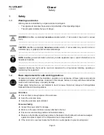
Warning notes are identified by a signal word and a pictogram.

The signal word indicates the severity and probability of the impending danger.

• 

The pictogram indicates the type of danger.

• 

---------------------------------------------------------------------------------------------------------------------------------------

WARNING

  identifies  a  potentially 

hazardous

  situation  which,  if  not  avoided,  may  result  in  serious 

injury.
---------------------------------------------------------------------------------------------------------------------------------------
---------------------------------------------------------------------------------------------------------------------------------------

CAUTION

 identifies a potentially 

hazardous

 situation which, if not avoided, may result in minor or 

moderate injury or property and environmental damage.
---------------------------------------------------------------------------------------------------------------------------------------
---------------------------------------------------------------------------------------------------------------------------------------

NOTE

 identifies general information which may include application tips or useful information but no 

hazardous situations.
---------------------------------------------------------------------------------------------------------------------------------------
---------------------------------------------------------------------------------------------------------------------------------------
Important  information  that  must  be  read  and  understood  by  all  personnel  installing,  operating  or 

maintaining this equipment.
---------------------------------------------------------------------------------------------------------------------------------------

1.2 

Basic requirements for safe working practices

All personnel involved with the installation, operation or maintenance of these tools must read and 

understand all safety instructions contained in this manual. Failure to comply with these instructions 

could result in serious injury or property damage.
These safety instructions are not intended to be all inclusive. Study and comply with all applicable 

National, State and Local regulations.
---------------------------------------------------------------------------------------------------------------------------------------

Work Area:

Ú


Ensure there is enough space in the work area.

Ú


Keep the work area clean.

Ú


Keep the work area well ventilated.

Personnel Safety:

Ú


Inspect the power cable for damage.

Ú


Make sure the power cable is securely attached to the tool.

Ú


Ensure a secure standing position and maintain balance.

Ú


Make sure the throttle is positioned relative to the head so the throttle will not become wedged  


against an adjacent object in the ON position due to torque reaction.

Ú


If the tool is to be reversed, locate the throttle in a neutral position to prevent entrapment.

Содержание 48ET Series

Страница 1: ...ps dotcotool com product category cleco tools cleco corded electric nutrunners cleco air tools cleco 48 series transducer control tubenut corded electric nutrunners Service Manual PL12EN 48ET 02 15 20...

Страница 2: ...of the DC electric right angle nutrunner as described in this manual indicates a required action indicates a list indicates a reference number from the exploded parts drawings Arial indicates an impor...

Страница 3: ...Maximum Torque Nm rounded to nearest Nm 20 20 Nm 30 30 Nm 40 40 Nm Head Size T2 20 Nm 15 ft lbs maximum output T3 30 Nm 22 ft lbs maximum output T4 40 Nm 30 ft lbs maximum output Socket Size refer to...

Страница 4: ...eral description 9 3 2 Operation and functional elements 9 3 3 Dimensional data 10 4 Accessories 12 5 Before initial operation 14 5 1 Ambient conditions 14 5 2 Power supply 14 5 2 1 TME 200 or m Pro 4...

Страница 5: ...48ETE Series Handle Air LB Tool Connector 24 10 3 48ET Series Motor Matrix Tool Connector 26 10 4 48ETE Series Motor Air LB Tool Connector 28 10 5 Single Stage Gearing Assembly 30 10 6 T2 Tube Nut He...

Страница 6: ...quirements for safe working practices All personnel involved with the installation operation or maintenance of these tools must read and understand all safety instructions contained in this manual Fai...

Страница 7: ...eye protection to protect against flying metal splinters Wear hearing protection Danger of injury by being caught by moving equipment Wear a hairnet Wear close fitting clothing Do not wear jewelry 1...

Страница 8: ...y statement 2 2 Transport Transport and store the 48ET in the original packaging The packaging is recyclable 2 3 Storage For short term storage less than 2 hours and protection against damage Place th...

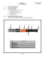
Страница 9: ...rushless motor Clockwise counterclockwise rotation High visibility LEDs 360 positionable head 3 2 Operation and functional elements This section describes the operational and functional elements of th...

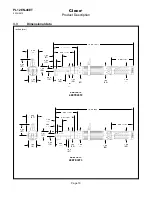
Страница 10: ...112 0 59 15 0 50 13 48ET20T2 48ETE20T2 1 85 47 5 16 131 4 68 119 1 58 40 1 82 46 2 61 66 1 63 41 1 52 39 1 68 43 1 00 25 1 60 41 2 23 57 2 24 57 16 66 423 4 07 103 0 60 15 0 60 15 48ET30T3 48ETE30T3 1...

Страница 11: ...2013 Cleco Product Description 3 3 Dimensional data continued inches mm 17 63 448 5 04 128 0 60 15 0 90 23 48ET40T4 48ETE40T4 2 00 51 5 80 147 4 68 119 1 58 40 1 82 46 3 11 79 1 60 41 1 52 39 1 68 43...

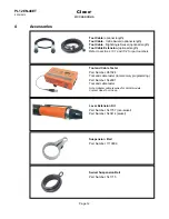
Страница 12: ...length Refer to sections 10 1 and 10 2 for part numbers Tool and Cable Tester Part Number 961024 Tool and cable tester tool memory programming Part Number 542991 Tool and cable tester Note Adapter cab...

Страница 13: ...ify the repeatability of nutrunners before being installed on a production line and are also an excellent means of testing nutrunners following repair The joint simulator can simulate and test the tor...

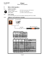
Страница 14: ...eries Nutrunner EN Description 115 VAC Standard TMEI 114 15 U 115 VAC DeviceNet TMEI 114 15 U ED 115 VAC ProfiBus TMEI 114 15 U EP TME 200 m Pro 400 Controller PL12 1300 Programming Notes 575708 Batte...

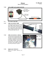
Страница 15: ...otherendofthecabletothetool connector on the controller Make certain the collar on the controller tool connector is pushed in towards the controller Align the connector patterns of the tool cable and...

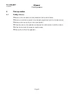
Страница 16: ...the tool and controller Make sure controller is powered on and properly programmed refer to controller manual Make sure the reverse ring is in the correct position Place the socket on the application...

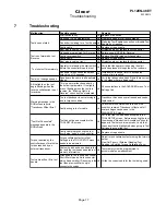
Страница 17: ...ab The tool tranducer is not returning to a zero torque condition Transducer has been over stressed and needs replacement Faulty wiring in tool or cable Check tool with different cable to see if the c...

Страница 18: ...g a customer specific maintenance plan Maintenance Interval Rundowns Daily Daily Visual inspection of all cables and connections Visual inspection of the 48ET tool Check the tool for excessive vibrati...

Страница 19: ...of 133 days W 1 2 3 W2 133 days Factor Value assumed in Service Schedule Description V V1 100 000 V2 500 000 V3 1 000 000 Number of rundowns after a maintenance measure is prescribed by Apex Tool Gro...

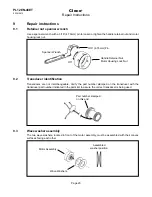
Страница 20: ...erchangeable Verify the part number stamped on the transducer with the transducer part number indicated in the parts list to assure the correct transducer is being used 9 3 Wave washer assembly The tw...

Страница 21: ...nts with the grease recommended on the gearing parts list pages DO NOT SUBSTITUTE GREASES 9 6 Tube Nut attachment lubrication Lubricate the angle head components with the grease recommended on the ang...

Страница 22: ...Spare Parts Black Connector 4 Pin 21 Models 48ET20T2 48ET30T3 48ET40T4 16 20 7 15 8 1 12 13 6 14 19 17 11 18 10 5 4 3 9 2 Red Connector 4 Pin Off Torque 15 18 ft lbs 20 25 Nm Torque 25 30 ft lbs 34 4...

Страница 23: ...e 542778 10M 10 meter cable 542778 15M 15 meter cable 542778 50M 50 meter cable 544056 1M 1 meter cable 544056 2M 2 meter cable 544056 3M 3 meter cable 544056 6M 6 meter cable 544056 8M 8 meter cable...

Страница 24: ...nnector Black Connector 4 Pin 21 16 20 7 15 8 1 12 13 6 14 19 17 11 18 10 5 4 3 9 2 Red Connector 4 Pin Off Torque 15 18 ft lbs 20 25 Nm Torque 25 30 ft lbs 34 41 Nm Torque 35 40 ft lbs 47 54 Nm Torqu...

Страница 25: ...3 meter cable 301866 4M 4 meter cable 301866 6M 6 meter cable 301866 8M 8 meter cable 301866 10M 10 meter cable 301866 15M 15 meter cable 301904 2M 2 meter cable 301904 3M 3 meter cable 301904 8M 8 m...

Страница 26: ...4 Pin White 2 Pin White 2 Pin Ground to Transducer to Amp Board Loctite 242 243 Loctite 242 243 3 5 1 6 2 2 1 3 10 1 7 8 4 4 10 1 6 10 3 48ET Series Motor Matrix Tool Connector Torque 4 6 in lbs 0 45...

Страница 27: ...e 10 3 1 Transducer Assembly 8 207340 1 Housing Quantity X Recommended Spare Parts quantity shown based on 1 5 tools in operation 10 3 48ET Series Motor Matrix Tool Connector Ref Number X Cleco Spare...

Страница 28: ...Pin White 2 Pin White 2 Pin Ground to Transducer to Amp Board Loctite 242 243 Loctite 242 243 3 5 1 6 2 2 1 3 10 2 7 8 4 4 10 2 6 10 4 48ETE Series Motor Matrix Tool Connector Torque 4 6 in lbs 0 45 0...

Страница 29: ...10 4 1 Transducer Assembly 8 207340 1 Housing Quantity X Recommended Spare Parts quantity shown based on 1 5 tools in operation 10 4 48ETE Series Motor Air LB Tool Connector Ref Number X Cleco Spare...

Страница 30: ...Page 30 PL12EN 48ET 02 15 2013 Cleco Spare Parts 10 3 10 4 10 9 2 4 5 7 6 1 3 8 L L L 10 5 Single Stage Gearing Assembly L Lubricate with Grease 541444 2 oz 56g 541445 16 oz 0 45 kg 12 11 13...

Страница 31: ...203749 3 6 Needle Bearing 7 541893 3 6 Planet Gear 21T 8 542793 1 Planet Carrier 9 541898 1 2 Extension Pinion 10 541044 1 2 Pinion Adapter 11 542794 1 Attachment Adapter includes Ref 12 12 500528 1...

Страница 32: ...be Nut Head Assembly L Lubricate with Grease 544076 2 oz 56g 544077 16 oz 0 45 kg N NOTE Always replace the Bevel Gear and Bevel Pinion at the same time since they should wear equally 23 24 8 14 21 11...

Страница 33: ...0 542895 1 Housing includes Ref 12 21 542962 1 1 Idler Gear 26T 22 Table 10 6 1 1 Output Gear 23 541821 1 Spacer 24 541426 1 2 Shim 002 25 541427 1 2 Shim 010 Quantity X Recommended Spare Parts quanti...

Страница 34: ...Models 48ET30T3 48ETE30T3 L Lubricate with Grease 544076 2 oz 56g 544077 16 oz 0 45 kg N NOTE Always replace the Bevel Gear and Bevel Pinion at the same time since they should wear equally 22 23 8 11...

Страница 35: ...Parts quantity shown based on 1 5 tools in operation T Teeth 10 7 T3 Tube Nut Head Ref Number X Cleco Spare Parts Table 10 7 Partial Thru Hex Thru Hex Double Thru Hex Partial Thru Double Hex 3 8 KS3EC...

Страница 36: ...Models 48ET40T4 48ETE40T4 L Lubricate with Grease 544076 2 oz 56g 544077 16 oz 0 45 kg N NOTE Always replace the Bevel Gear and Bevel Pinion at the same time since they should wear equally 2 23 9 17 1...

Страница 37: ...ble 10 8 Partial Thru Hex Thru Hex Double Thru Hex Partial Thru Double Hex 1 2 KS4EE00 KS4EE01 KS4EE02 KS4EE03 9 16 KS4EF00 KS4EF01 KS4EF02 KS4EF03 5 8 KS4EG00 KS4EG01 KS4EG02 KS4EG03 11 16 KS4EH00 KS...

Страница 38: ...kg in mm in mm in mm in mm 48ETE20T2 1 2 7 4 14 8 10 20 1425 16 9 430 4 4 2 0 1 42 36 0 55 14 0 280 7 0 53 13 48ETE30T3 3 4 11 1 22 1 15 30 1030 16 6 422 4 5 2 0 1 65 42 0 59 15 0 475 13 0 73 19 48ET...

Страница 39: ...nty repairs All warranty repairs are to be performed by an authorized Apex Tool Group service center Contact your local representative for assistance with warranty repair claims 13 Disposal Injuries a...

Страница 40: ...bH Co OHG 2865 152nd Avenue N E 3990 East Market Street 5925 McLaughlin Road Industriestra e 1 Redmond WA 98052 York PA 17402 Mississauga Ont L5R 1B8 73463 Westhausen Tel 425 497 0476 Tel 717 755 2933...

Отзывы: