background image

7

Revision date: 06.04.10

End Panel Installation

END PANEL INSTALLATION (continued)

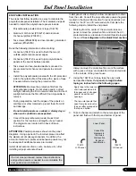
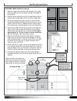
Measure between the side H-channel sections of the center 

7. 

panel (or panels) and cut H-channel to length. See diagrams 

for panel size.
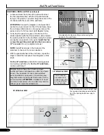
Install H-channel along the top of the installed lower panel (or 

8. 

panels). Upper panels slide into this H-channel (diagram B).
Set the first upper panel in place into the H-channel of the 

9. 

lower panel and align the edges with the lower panel. 

Do not 

attach at this time

. Have an assistant hold the panel against 

the end frame. 

Do not install panels on windy or stormy days.

Using the end rafter end cap as a guide, trace along the end 

10. 

cap to mark the panel height. Set the panel on a protected 

surface and cut the panel to the correct size. 

Cut the panel 

approximately 1/8" shorter to allow for easier installation.


Tape the cells at the upper end using vent tape.
Measure the distance along the vertical edges of the panel 

11. 

sides and cut H-channel to the measured length. 

H-channel, 

when installed properly, is positioned under the end cap with 

the panel. Use the end cap as a guide to properly cut the 

upper end of the H-channel.

Set the panel back in place, 

12. 

with the UV-protected side facing 

to the outside,

 against the end wall and install the H-channel 

along the edges. Top end of the side H-channel fits under the 

lip of the end cap and slides onto the polycarbonate panel.
Verify that the panel is square and in the desired position, 

13. 

and attach the panel to the end frame using Tek screws and 

washers.

H-Channel

B

Upper 

Panel

Lower 

Panel

GROUND LEVEL

6' x 8'


Panel

6' x 8'


Panel

Measure here 

for Step 7.

6' x 8'


Panel

6' x 8'


Panel

Brace

Brace

C

B

Trim  

excess panel

Trim  

excess panel

Actual end frame and panels may 

differ from frame shown. Consult the 

panel diagrams located in the Quick 

Start section for the end kit ordered.

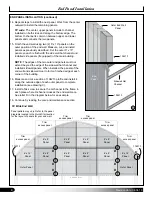
35' Wide End Wall

Install Tek screws and 

washers through the 

panel and into the end 

wall braces. Evenly 

space the screws at 12".

Trim H-channel 

as needed to fit 

under the lip of the 

end cap attached 

to the end rafter.

End Rafter

End Cap

Panel

C

Содержание R030B00008

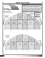
Страница 1: ... frame Actual panel positions and sizes for your end panel package may differ from what is shown Photo is used as an example only Consult the diagrams in the Quick Start section of this guide for your building to see the panel sizes and layout ClearSpan Twin Wall Polycarbonate End Panel Kit 30 Wide 35 Wide STK R030B00008 30 Wide R035B00008 35 Wide ...

Страница 2: ...d proceed as instructed In most instances the end frame and door frame are constructed before end panels are installed This allows for the placement of panels as determined by the position of the door or doors It is the responsibility of the owner contractor to adjust the position of the end panels based on the end frame and the position of the installed door or doors Consult the services of a qua...

Страница 3: ...must seek the help of a qualified contractor REQUIRED TOOLS The following list identifies the main tools needed to assemble the end wall Additional tools and supports may be needed depending on the structure location and application Tape measure or measuring device Fine point marker to mark the location on frame and panels Variable speed drill and impact driver cordless with extra batteries works ...

Страница 4: ...me parts are not shown UNPACK AND IDENTIFY PARTS The following steps will ensure that you have all the necessary parts before you begin to install the end panels Unpack the contents of the shipment and place 1 where you can easily inventory the parts Refer to the Bill of Materials Spec Sheets Verify that all parts listed on the Bill of Materials Spec 2 Sheets are present If anything is missing or ...

Страница 5: ... section for the location and lengths of each panel The diagrams are located at the back of these instructions ATTENTION Position panels as shown on the panel diagrams Using a panel in the incorrect place can affect the placement of subsequent panels In addition the amount of aluminum profile used between panels may not be adequate if additional seams are created Install all accessories fans vents...

Страница 6: ...peat the 6 steps to install the next panel See diagrams on this page For the 30 wide frame install all remaining panels and continue with Step 16 For the 35 wide frame continue with Step 7 Diagram below shows the 35 wide end wall Actual end frame and panels may differ from frame shown The installation of doors also will affect panel installation and position Consult the panel diagrams located in t...

Страница 7: ...ides and cut H channel to the measured length H channel when installed properly is positioned under the end cap with the panel Use the end cap as a guide to properly cut the upper end of the H channel Set the panel back in place 12 with the UV protected side facing to the outside against the end wall and install the H channel along the edges Top end of the side H channel fits under the lip of the ...

Страница 8: ...hen installed the panels of the end wall and sidewall meet to form a finished edge at each corner of the building Measure and cut a section of 104213 profile and install it 16 along the outside edge of each outer panel to complete installation see drawing C Install a Tek screw to secure the H channel to the frame in 17 each place where H channel crosses the end wall brace See letter D in the diagr...

Страница 9: ...good condition Replace damaged panels if needed Check connections and all fasteners to verify that they remain tight Check the contents of the shelter to verify that nothing is touching the polycarbonate panels that could cause damage Inspect the end wall frequently and regularly to ensure that it remains secure and in good repair Replace broken or missing components immediately If the shelter is ...

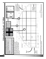
Страница 10: ...finished corner Diagrams in this section include sidewalls GROUND LEVEL Install Tek screws and washers through the panel and into the end wall brace Evenly space the screws at 12 6 x 8 Panel 102530 4 x 8 Panel 102908 4 x 8 Panel 4 x 8 Panel 4 x 8 Panel 6 x 8 Panel 6 x 12 Panel 102531 6 x 8 Panel 6 x 8 Panel 6 x 12 Panel Panel Kit for 30 Wide Frame R030B00008 Sidewall Panel Sidewall Panel GROUND LE...

Страница 11: ...e on the bottom edges of the lower panels and along the top edges of the upper panels after these are cut to fit Tape the top and bottom of the outer panels marked with an X All polycarbonate panels to be installed with UV protected surface toward the outside of the shelter X X X X X X Install 104213 profile along this edge of the end panel Install 104213 profile along this edge of the end panel T...

Страница 12: ...ding door installation Diagram below shows the installed sidewall hat channel used for the installation of the sidewall polycarbonate panels of the main building All polycarbonate panels to be installed with UV protected surface toward the outside of the shelter Trim H channel as needed to fit under the lip of the end cap attached to the end rafter X X X X X X Install 104213 profile along this edg...

Страница 13: ...13 Revision date 06 04 10 Notes This page is reserved for customer notes ...

Отзывы: