


W i r e l e s s I F B / C u e S y s t e m
3 - 3
Finally, plug the correct external in-line or wall-type power supply for your
operating voltage into the AC power outlet. Then, insert the DC power
connector into the power jack located on the rear panel of the UPX-10. The user
may wish to provide DC power from a source other than the provided
wall-mounted power supply. In this case, c12 to +20 VDC (0.3 A
minimum) to the power connector on the rear of the UPX-10. A compatible
mating connector is the Switchcraft 760. When connecting external DC,
carefully observe the following polarity rules:
Power supply negative (-) to the outer conductor.
Power supply positive (+) to the inner conductor.
CAUTION: No internal circuit protection fuse is provided with the UPX-10.
The available current from the provided power supply is internally
impedance-limited and thermal-limited and therefore does not require
additional circuit protection. If the user provides DC power to the UPX-10
from a source other than the provided wall-mounted power supply, external
fusing provided by the user is strongly advised. Consult the Clear-Com factory
for more information.
The installation of the UPX-10 is now complete, and the unit is ready for
adjustment and operation.
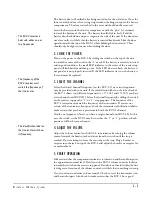
ADJUSTING THE SETTINGS
There are no user-serviceable adjustments located inside the UPX-10. In
addition, normal setup and operation does not require internal access. Refer all
service and internal adjustments to qualified service personnel. Specifically, the
user may not make adjustments to the transmitter module. See Chapter 4,
“Troubleshooting” for more information.
The adjustment procedure below is for the normal balanced mic-level or
line-level input mode. The procedure for setting up the unit for use with
intercom systems is essentially identical, except that the mic/line switch is not
needed and is nonfunctional.
Initial Settings
Select the desired type of audio dynamic range limiting by means of the
three-position slide switch found on the rear panel. The recommended setting
for intercom or IFB use is “Soft ALC.” Other positions may be tried. The “Hard
ALC” position provides about 35 dB range of automatic level control with fixed
gain at low input levels to reduce system noise. The “Linear” position provides
no dynamic range limiting at all. The “Soft ALC” position provides soft, 2:1
logarithmic gain compression. Set the “low” and “high” frequency compensation
controls to the mid or “0” position.
•
Caution
: No internal
circuit protection fuse is
provided with the
UPX-10.
• Normal setup and
operation does not
require internal access to
the UPX-10.
• Refer all service and
internal adjustments to
qualified service
personnel.
Содержание RCV-2
Страница 1: ...UPX 10 TRANSMITTER I N S T R U C T I O N M A N U A L WIRELESS IFB CUE SYSTEM RCV 2 RECEIVER...
Страница 4: ...W i r e l e s s I F B C u e S y s t e m...
Страница 6: ...W i r e l e s s I F B C u e S y s t e m...
Страница 10: ...W i r e l e s s I F B C u e S y s t e m 2 4...
Страница 23: ...I M F 1 0 2 I N T E R F A C E M O D U L E F R A M E 6 3 NOTES...
Страница 24: ...I M F 1 0 2 I N T E R F A C E M O D U L E F R A M E 6 4 NOTES...