background image


11 

Clear-Com HME DX210 Operating Instructions 


2.4  Interfacing with 2-Wire or 4-Wire Intercoms 


2-Wire Intercom Interface: 

The following 2-wire setup is for Channel 1 (IC1). 

If applicable, repeat for Channel 2 (IC2).


● 

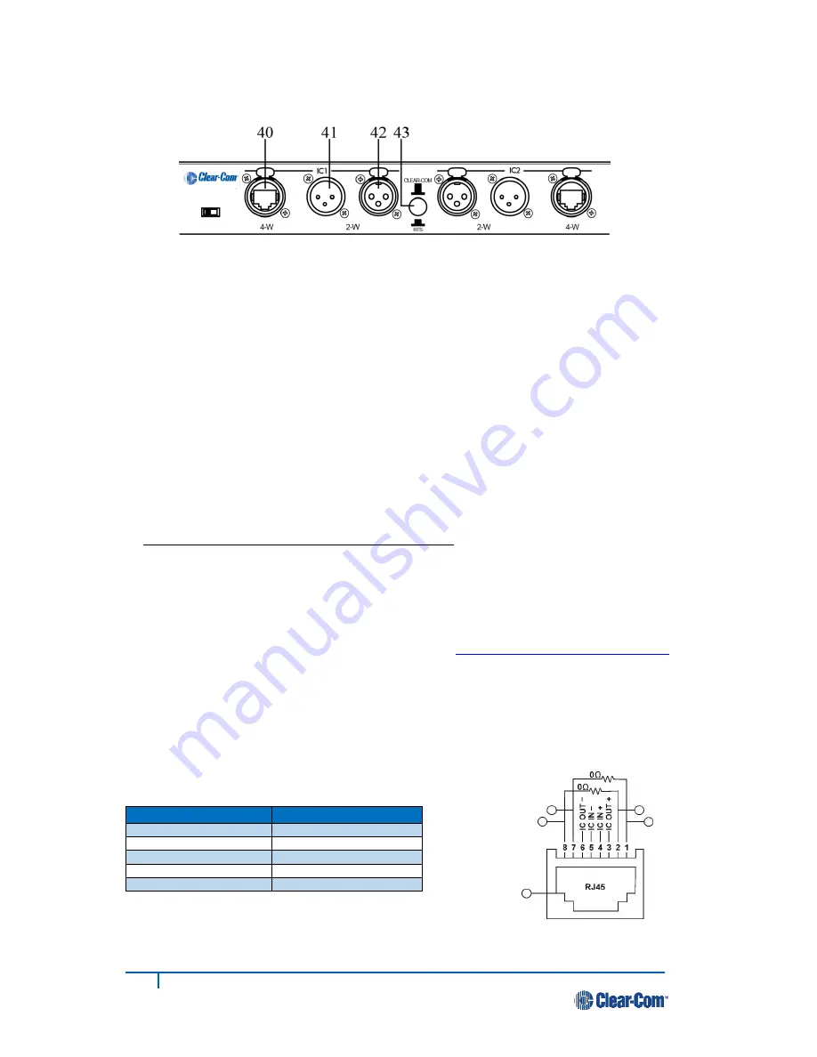
If using a 2-wire intercom

 with the DX210, plug the appropriate male or female connector into the 

base station 

2-W

 connector at #

41 

or #

42


● 

Depending on whether you are using a Clear-Com

®

 or RTS

®

 compatible 2-wire intercom system, 

position the 

CLEAR-COM 

RTS 

button (#

43

) as follows: 


In position = RTS Mode  Out position = Clear-Com Mode 


● 

Press the 

IC1


SELECT 

button (#

12

) on the front panel of the base station. The 

2-W 

light (#

10

) next to 

the button should turn green. 


NOTE:

 If no power is detected at the 

2-W

 connector, the 

2-W

 light will turn red and no audio will be 

passed through. Plugging in a connection to a Clear-Com or RTS power supply will turn the light green 
and operation will begin. 

● 

Be sure there are no open microphones on the wired intercom. 

If users are wearing headsets, please 

notify them of the impending audio sweep prior to auto nulling.


Press and hold the 

AUTO NULL

 button for two seconds. To press the 

AUTO NULL 

button, insert a 

pen or similar pointed object into the 

AUTO NULL 

hole on the front panel of the base station. An audio 

sweep will be heard for 25 seconds on the wired Beltpacks. (The 

2-W 

light (#

10

) next to the button 

should turn amber, then green.) 

● 

Adjust the 2-W intercom receive and send levels with the 

IC1 2-W INPUT

 control (

#9

) and 

OUTPUT


control (

#8

).  

NOTE:

 If you are not connecting other equipment, go on to 

System Operation, section 3, page 14.


4-Wire Intercom Interface: 

The following 4-wire setup is for Channel 1 (IC1). 

Repeat for Channel 2 (IC2) if applicable. 

● 

If using a 4-wire intercom

 with the DX210, plug it into the base station 

IC1


4-W 

connector (#

40

). 

● 

Press the respective 

SELECT

 button until the 

IC1


4-W 

light (#

13

) next to the button turns on. 

● 

Adjust the 4-wire intercom receive and send levels  
with the 

IC1


4-W


INPUT 

and 

OUTPUT

 (#

14

 & 

15

)


controls. 

RJ45 Connector Pins 

Designation 

Pins 1, 2, 7 and 8 

N/C (reserved) 

Pin 3 

Intercom Out + 

Pin 4 

Intercom In + 

Pin 5 

Intercom In 

– 

Pin 6 

Intercom Out 

– 

 
NOTE:

 Simultaneous 2-wire and 4-wire communication is possible.  

Both groups of intercom users can communicate with the base station operator, but not with each other. 

Base station rear panel 

Содержание HME DX210

Страница 1: ...Clear Com HME DX210 Dual Channel Wireless Intercom Operating Instructions 400G751 Rev B 1 27 17 ...

Страница 2: ......

Страница 3: ... without prior written authorization of Clear Com an HME Company Clear Com Offices are located in California USA Cambridge UK Montreal Canada and Beijing China Addresses and contact information can be found on Clear Com s corporate website at www clearcom com Clear Com Contacts Americas and Asia Pacific Headquarters California United States Tel 1 510 337 6600 Email CustomerServicesUS clearcom com ...

Страница 4: ...cations were met Base Station Antenna minimum safe distance 7 9 inches 20 cm at 100 duty cycle Base Station Antenna gain This device has been designed to operate with an antenna having a maximum gain of up to 7dBi Antenna mounting The antenna s used for the base transmitter must be installed to provide a separation distance of at least 7 9 inches 20 cm from all persons and must not be co located o...

Страница 5: ...n points reuse and recycling of specified percentages per the WEEE requirements Instructions for Disposal of WEEE by Users in the European Union The symbol shown below is on the product or on its packaging which indicates that this product was put on the market after August 13 2005 and must not be disposed of with other waste Instead it is the user s responsibility to dispose of the user s waste e...

Страница 6: ...3 3 System Operation 14 3 1 Base Station Operation 14 3 1 1 Digital Radio Controls and Indicator Lights 14 3 1 2 Local Headset Connector Controls and Indicator Lights 14 3 2 Beltpack and All in One Headset Operation 15 3 2 1 Power On Off 15 3 2 2 ISO Isolate and IC1 IC2 Intercom 15 3 2 3 Operating Modes 15 3 2 4 Volume Up Down 15 3 2 5 Adjusting Microphone Gain 16 3 2 6 Adjusting BP210 Beltpack Si...

Страница 7: ...usly In the single channel mode any 4 Beltpacks or all in one headsets can transmit simultaneously This number can be increased by connecting up to 3 additional base stations The DX210 has 4 wire and auxiliary audio connections and supports both Clear Com and RTS cabled 2 wire intercom systems The DX210 operates in the 2 4GHz band and has provisions for Spectrum Friendly co existence with other de...

Страница 8: ...3 IC2 4 W indicator light AUXILIARY CONTROLS 24 AUX IC1 IC2 INPUT ASSIGN indicators 25 AUX INPUT ASSIGN button 26 AUX INPUT level adjust 27 AUX IN indicator light 28 AUX INPUT OUTPUT SELECT button 29 AUX OUT indicator light 30 AUX OUTPUT level adjust HEADSET CONTROLS 31 HEADSET IC1 IC2 ISO indicator lights 32 HEADSET IC1 IC2 ISO SELECT button 33 HEADSET VOLUME knob 34 HEADSET TALK indicator light ...

Страница 9: ...4 ISO Isolate button 5 IC1 Intercom 1 button 6 PWR Power button 7 Volume up button 8 Volume down button 9 Battery 10 Battery release latch 1 5 All In One Headset WH220 1 IC1 button 2 ISO Isolate button 3 Volume up button 4 IC2 button 5 Volume down button 6 Power mode light 7 Microphone 8 Power button 9 Battery 10 Battery release latch ...

Страница 10: ...arger Connect the AC power supply cable connector to the power connection on the battery charger and turn clockwise to lock in place Connect the AC power cord connector to the AC power supply unit Connect the AC power cord to an electrical outlet The red lights on the charger will come on briefly and then the yellow lights will come on and stay on 2 1 2 Charge Batteries Up to four batteries can be...

Страница 11: ...s in a charging port a yellow light on steady next to it means CHARGE FAILED If this happens follow the instructions on the side of battery charger A red CHARGING light next to a battery port stays on while a battery in the port is charging A green READY light next to a battery port goes on when a battery in the port is fully charged Store fully charged batteries in storage ports NOTE Batteries sh...

Страница 12: ...ge ports Insert a battery in each of four Charging ports until it clicks in place A yellow light next to a Charging port indicates that the port is EMPTY A red light next indicates that the battery port is CHARGING A green light indicates that the battery is READY A steady yellow light indicates that the CHARGE FAILED If a charge fails refer to the instructions on the side of battery charger A fla...

Страница 13: ...h 47 for the base station to operate in single or dual channel mode In single channel mode all wireless users will be able to hear one other Up to four users can talk simultaneously In dual channel mode there are two separate audio channels enabling two groups of users to independently communicate with each other Up to three users can talk simultaneously NOTE Any time the mode is changed the unit ...

Страница 14: ...tpacks and all in one headsets can be registered to a single base station at one time 2 3 1 Set Up Beltpack and All in One Headset NOTE If multiple base stations will be used or if interference is present such as Wi Fi interference refer to Base Station Registration and Interference Avoidance in Appendix D and E on pages 24 through 26 Before registration set up all beltpacks and all in one headset...

Страница 15: ...tpack Version Begin registration Registration complete After a delay of about 15 seconds the STATUS display will show the ID number assigned to this beltpack or all in one headset for about 10 seconds NOTE ID numbers are assigned sequentially as 0 thru 9 A b C d and E The power light on the beltpack or all in one headset will remain on steady green If registration failed A voice message in the hea...

Страница 16: ...l in one headsets are turned off and on again For Setting Press Hold while you Press Release the Power button ISO restrict on IC1 button ISO restrict off IC1 and ISO buttons Handsfree on selected button s IC1 and or IC2 and or ISO and volume up buttons Handsfree off selected button s IC1 and or IC2 and or ISO and volume down buttons Listen Only mode on volume down button Listen Only mode off volum...

Страница 17: ...lling Press and hold the AUTO NULL button for two seconds To press the AUTO NULL button insert a pen or similar pointed object into the AUTO NULL hole on the front panel of the base station An audio sweep will be heard for 25 seconds on the wired Beltpacks The 2 W light 10 next to the button should turn amber then green Adjust the 2 W intercom receive and send levels with the IC1 2 W INPUT control...

Страница 18: ...levels coming in from beltpacks and all in one headsets or a local headset as it goes out to 2 W and 4 W equipment connected to the base station The AUTO NULL button is used to eliminate echo caused by mismatched line characteristics of an external 2 W system CAUTION Before pressing the AUTO NULL button be sure there are no open microphones on the wired system Use a pen or similar pointed object t...

Страница 19: ...UX OUT audio to the auxiliary equipment from the ISO channel of the beltpack all in one headset or local headset The IN and OUT lights come on green to indicate the selection The INPUT and OUTPUT controls adjust auxiliary inbound and outbound audio levels The SELECT button on the left 25 is used to select IC1 or IC2 or both as the destination for AUX IN audio The IC1 and or IC2 INPUT ASSIGN lights...

Страница 20: ... for the selection you made IC1 and IC2 communication will be heard by wireless users on the respective channel as well as users wired into 2 W and 4 W connections ISO is heard in both wireless channels and AUX OUT if activated NOTE When the ISO button is pressed ISO RELAY 50 is activated The TALK button is used for communication from the local headset to the selected channel For open communicatio...

Страница 21: ...Operation In PTT operation audio is transmitted only while you are pressing and holding the IC1 IC2 or ISO button When you release the button transmission stops Hands free Mode Operation Quickly press and release the IC1 IC2 or ISO button to latch the transmitter on Talk and listen as in a normal telephone conversation Quickly press and release the same button again to unlatch and end the conversa...

Страница 22: ...g down the IC1 button in the normal operating mode To decrease side tone Press the volume down button while holding down the IC1 button in the normal operating mode NOTE The side tone setting will be indicated in numbers by a voice prompt Default setting is Max 3 2 7 Using WH220 All In One Headset Lights Off Mode The Lights Off mode can be used to avoid audience distraction from the lights on the ...

Страница 23: ... is selected in the HEADSET section of the base station front panel If using a Beltpack or All In One Headset press the desired IC button People on the RTS Clear Com systems cannot hear me or I cannot hear them Be sure the cables are securely connected and the 2 wire intercom is on If using the local headset be sure the desired IC setting is selected in the HEADSET section of the base station fron...

Страница 24: ... 3M XLR 3F externally switchable RTS or Clear Com mode 200Ω level adjustable null adjustable to 50dB attenuation typical Auxiliary Input XLR 3F 6 35 mm combo jack 600Ω balanced level adjustable Auxiliary Output XLR 3M 600Ω balanced level adjustable Headset Connector 4 pin mini DIN Electret microphone Headset Output 200mW into 32Ω Antenna Type External wave dipole R TNC connector RX TX horizontal v...

Страница 25: ...tor 4 pin mini DIN Microphone Electret Headset Output 160mW into 32Ω Controls Power Volume up Volume down IC1 IC2 ISO Indicators Dual color LED red green Communication Security 64 bit encryption System Distortion 2 BELTPACK TRANSMITTER Type Frequency Hopping Spread Spectrum Transmit Power 100mW burst Transmission Modes Momentary or latch Modulation Type Gaussian filtered FSK TDMA Frequency Stabili...

Страница 26: ...lectret Headset Output 160mW into 32Ω Controls Power Volume up Volume down IC1 IC2 ISO Indicators Dual color LED red green Communication Security 64 bit encryption System Distortion 2 HEADSET TRANSMITTER Type Frequency Hopping Spread Spectrum Transmit Power 100mW burst Transmission Modes Momentary or latch Modulation Type Gaussian filtered FSK TDMA Frequency Stability 13 ppm Harmonics Spurious Exc...

Страница 27: ...reen IC2 TX OFF Blinks Green ISO TX Blinks Green Blinks Green Low battery Appropriate channel light Blinks Red when in idle mode WH220 All In One Headset Indicator Lights WH220 Condition Main Indicator Light Boom Indicator Light IC1 Idle Steady Green Off IC1 TX Blinks Green Steady Green IC2 Idle Steady Red Off IC2 TX Blinks Red Steady Green ISO TX Blinks Red or Green depending on previous Mode Ste...

Страница 28: ...y chaining the cable connectors must be 3 pin XLR If using 4 wire connection use cable with In Out crossed as shown to the right An Ethernet crossover cable will not work If using 2 Wire connections open each base station and set jumpers JP1 IC1 and or JP2 IC2 in all base stations to ON for power detect bypass Set jumpers JP5 IC1 and or JP6 IC2 in only one base station per channel for termination ...

Страница 29: ... and the local headset will still receive ISO communication To enable this feature set JP4 to ON Power Detect Bypass In the event the DX210 base station is connected to a 2 W line which does not contain power such as when multiple base stations are daisy chained JP1 IC1 and or JP2 IC2 need to be set to ON to enable 2 W interface for the respective channel s to come on WARNING If no termination is ...

Страница 30: ... page 9 Turn each beltpack or all in one headset off after registering it Power on one secondary base station The STATUS display will show a double bar indicating the secondary base station is ready to be registered Base station ready to be initialized Small o indicates primary base station is open for registration Press the REG register button on the primary base station The STATUS display will s...

Страница 31: ...ue holding the CLR BND button after you release the RESET button until the clear code c lower case appears on the STATUS display Any beltpacks and all in one headsets associated with the old primary will have to be registered to the new primary after secondary base station registration All beltpacks and all in one headsets associated with secondary base stations also have to be registered again If...

Страница 32: ...e still holding the CLR BND button press and hold the REG button and wait until a L H or A appears and then release both buttons NOTE Base stations are shipped in the A default position Press the CLR BND button to cycle through parts of the frequency band L Low end H High end and A All and stop on the desired setting Wait until c appears on the display NOTE c will only appear on the STATUS display...

Страница 33: ...cations in close proximity can result in additional risk for trouble free operation The new technology further ensures that products do not add interference to the spectrum for other essential wireless services in the vicinity such as DMX controlled lighting Avoiding Wi Fi Interference To avoid interference with Wi Fi systems it is recommended to set the Wi Fi system to something other than channe...

Страница 34: ...inuous process of scanning for used frequencies and updating the list of good channels The Clear Com system utilizes 46 discrete frequencies or channels within the 2 4 GHz spectrum in order to communicate voice and data The process of deciding which channels should be used is a 3 stage process The process includes scanning for occupied channels the broadcast of a channel exclusion list and the use...

Страница 35: ...lot of channels this takes longer as the communicator does not have the exclusion list and looks for the base on channels it is not using Initial sync time increase For the same reason registration may take longer the initial headset sync on power up may take longer Required AFH Equipment In order to utilize AFH the base station must be set to European mode The headsets and belt packs must also be...

Страница 36: ...on should be set to operate in the region of the 2 4 GHz band where the Wi Fi access point is not operating For example if the Wi Fi access point is set to Wi Fi channel 1 the base station should be set to operate in the High band If the Wi Fi access point is set to channel 11 the base should be set to operate in the Low Spectral efficiency Wi Fi systems employ a standard sometimes referred to as ...

Страница 37: ...31 Clear Com HME DX210 Operating Instructions Audio Routing Diagram ...

Страница 38: ...ully linked with a primary base You can register beltpacks in this mode Two horizontal bars indicate that the base is in secondary mode and ready to be synced with a primary base You cannot register beltpacks in this mode you must sync to a primary base first Three horizontal bars indicate the base is in secondary mode and has been linked with a primary base but the primary base is no longer avail...

Страница 39: ...ase c will appear when the registry on the base station is cleared To clear the registry power down the base Hold down the CLR BND or RESET REGISTRATION button first and then power the base on when you see the 8 on the LED display release the CLR BND or RESET REGISTRATION If done successfully you will see a small c on the LED display NOTE The display indicates that the registry of a base station h...

Страница 40: ...ectrum Friendly option Hold down the CLR BND or RESET REGISTRATION button first then press and hold down the REG or REGISTER BELTPAC button till you see the letter A or L or H Then release both buttons and quickly press the CLR BND or RESET REGISTRATION to cycle through the A or L or H options Stop at your selection and wait for the LED display to go blank and a lower case c will appear on the sta...

Страница 41: ...板 XCVR PCB G27739 4A1 X O O O O O AC40 电池充电器 AC40 G27368 X O O O O O 电源器 453G008 CCC P S X O O O O O O 表示该有毒有害物质在该部件所有均质材料中的含量均在SJ T11363 2006标准规定的限量要求以下 O Indicates that this toxic or hazardous substance contained in all of the homogeneous materials for this part is below the limit requirements in SJ T11363 2006 X 该有毒有害物质至少在该部件的某一均质材料中的含量超出SJ T11363 2006标准规定的限量要求 X Indicates that this toxic or ha...

Страница 42: ... 1 306G101 1 X O O O O O 对讲机套 Pouch 107G065 O O O O O O 电池 Battery 104034 O O O O O O O 表示该有毒有害物质在该部件所有均质材料中的含量均在SJ T11363 2006标准规定的限量要求以下 O Indicates that this toxic or hazardous substance contained in all of the homogeneous materials for this part is below the limit requirements in SJ T11363 2006 X 该有毒有害物质至少在该部件的某一均质材料中的含量超出SJ T11363 2006标准规定的限量要求 X Indicates that this toxic or hazardous substan...

Страница 43: ...O O O O O 电池 Battery 104034 O O O O O O O 表示该有毒有害物质在该部件所有均质材料中的含量均在SJ T11363 2006标准规定的限量要求以下 O Indicates that this toxic or hazardous substance contained in all of the homogeneous materials for this part is below the limit requirements in SJ T11363 2006 X 该有毒有害物质至少在该部件的某一均质材料中的含量超出SJ T11363 2006标准规定的限量要求 X Indicates that this toxic or hazardous substance contained in at least one of the homogeneou...

Отзывы: