background image

     Troubleshooting

 (continued) 

22 

OZONE GENERATOR 

– 

continued


PROBLEM/SYMPTOM 

POSSIBLE CAUSE 

 SOLUTION 

 
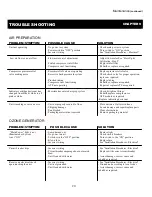
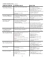
Unit flooded with water 

- Defective check valve 

 - Replace check valve(s) 

Ozone smell detected in or 


- Assess damage, repair as required near 

ozone generator                                    - Insufficient vacuum at venturi 

- Adjust injector See “Start- Up & 


   Calibration - Steps 1-4” 


- Loose internal fittings 

 - Check all fittings, tighten as needed 


- Defective O-ring seals in reaction chamber(s) 

 - Check & replace as required 


- Defective dielectrics 

 - Check & replace as required 


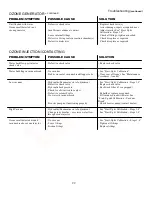
OZONE INJECTION/CONTACTING 


PROBLEM/SYMPTOM 

POSSIBLE CAUSE 

 SOLUTION 

 
Water backflow past injector 

- Defective check valve 

- Replace check valve 

check valve 
 
Water bubbling in vacuum break 

- No vacuum 

- See “Start-Up & Calibration” 


- Debris on seat of vacuum break flapper valve 

- Clean seat of flapper. See “Maintenance 


Procedures - Annual”   


Low vacuum 

- Hydraulics/Pneumatics out of adjustment 

 - See “Start-Up & Calibration - Steps 1-4” 


- Defective check valve 

 - Replace check valve


- Hydraulic back pressure 

 - Back wash filter (if so equipped) 


- Check for obstruction in venturi 


- Defective solenoid valve 

 - Rebuild or replace as required  


- No water in vacuum break 

- Fill vacuum break with water See 


 “Start-Up and Calibration – Vacuum 


 Break” 


- Booster pump not functioning properly 

- Check booster pump (contact dealer) 


High Vacuum 

- Hydraulics/Pneumatics out of adjustment 

 - See “Start-Up & Calibration – Steps 1-4” 


- Change in hydraulics – excessive water flow 

 - See “Start-Up & Calibration – Steps 1-4” 


 through ozone injector 


Ozone smell detected around 

- No vacuum 

- See “Start-Up & Calibration – Steps 1-4” 

vacuum break or ozone injector 

- Loose fittings 

- Tighten all fittings 


- Broken fittings 

- Replace fittings   


Содержание CD1500P

Страница 1: ...s a component only Tested and certified by WQA to NSF ANSI 50 as a component only ClearWater Tech LLC Integrated Ozone Systems 850 E Capitolio Way San Luis Obispo Ca 93401 805 549 9724 Fax 805 549 030...

Страница 2: ...o achieve the ozone output and longevity of the ozone generator A pounds per square inch PSI regulator must be installed when using plant air feed gas This regulator must be set to a maximum of 10 PSI...

Страница 3: ...m of extremely tiny bubbles These bubbles must be as small as possible in order to increase the ratio of bubble surface area to the amount of ozone entering the water Depending on the application and...

Страница 4: ...s detectable at very low concentrations 0 02 ppm which is far below OSHA s maximum permissible exposure level of 0 1 ppm HIGH VOLTAGE WARNING CLEARWATER TECH OZONE GENERATORS OPERATE AT HIGH VOLTAGE D...

Страница 5: ...ipment 7 The electrical supply for this product must include a suitably rated switch or circuit breaker to open all ungrounded supply conductors to comply with Section 422 20 of the National Electrica...

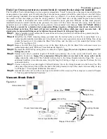
Страница 6: ...justment chemical injection point must be located downstream of the residual sanitizer injection point if so equipped In a Full Flow plumbing configuration see Figure 4 2 without recirculation locate...

Страница 7: ...ical print or as dictated by equipment layout and serviceability considerations Do not secure booster pump and contact vessel to housekeeping pads at this point Dry fit plumbing as appropriate to insu...

Страница 8: ...he two holes for mounting the L bracket to the wall The bracket should be located so that the 6 clamp assembly will be approximately 12 from the top of the contact column Drill a 1 2 hole at each of t...

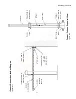
Страница 9: ...Base Flange Gasket Base Flange Nuts Washers 8ea Contact Column Exploded View Figure 4 4 Contact Column Installation Diagram Figure 4 3 6 Clamp Assembly Bolts nuts with bolt Nut washers 2ea Unistrut cu...

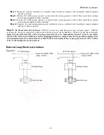
Страница 10: ...AWG wire located at the bottom panel of the ozone generator see Appendix Section A can be interfaced to any control device i e pressure switch vacuum switch flow switch float switch ORP controller PPM...

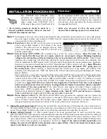
Страница 11: ...Preparation System Power 120VAC systems only plug the power cord into main power 240VAC systems only the power cord must be hard wired to the main power source Black L1 White L2 N and Green Ground No...

Страница 12: ...y Step 3 Mount indicator cartridge on a suitable flat surface using the Clic mounting clamps provided Notes The indicator cartridge must be mounted vertically The indicator cartridge does not have a d...

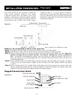
Страница 13: ...vertical position and the drain holes are below the level of the ozone generators ozone outlet fitting One clamp should be located so it fits around the Riser Tube Elbow and the other so it fits aroun...

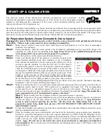
Страница 14: ...the injector manifold until the needle moves into the green zone If the needle is in the red zone on the vacuum in Hg side of the gauge gradually open the ball valve on the injector manifold until the...

Страница 15: ...e it will open causing a loss of vacuum A loss of vacuum means ozone cannot flow from the vacuum break which in turn can cause an ozone leak Note If the vacuum break must be refilled with water discon...

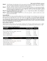
Страница 16: ...ary by following the steps outlined in the Start Up Calibration section Ozone Generator Indicator Lights Check the Main Power indicator light at the bottom of the ozone generator and Ozone LED s at th...

Страница 17: ...one output LED will illuminate when ozone drive is being generated The LED will also pulse as the output increases or decreases with either the Manual Ozone Output Control located on the bottom of the...

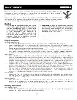
Страница 18: ...and or operating conditions in the equipment area will dictate the required frequency of this procedure Ozone Generators Cooling Fan Filters Clean or replace the cooling fan filter elements as requir...

Страница 19: ...ielectric approximately 1 2 from either end of the glass making sure it is rolled squarely Step 6 Slide the dielectric into the heat sink cathode assembly Seat the dielectric into the O rings of the n...

Страница 20: ...normal for some water to be flowing from the injector during this procedure Contact Vessel Cleaning Contact Column only Inspect the diffuser slots at the top of the contact column riser tube If they...

Страница 21: ...place compressor or pink or white ATF module as required Replace indicating desiccant Unit is making excessive noise Unit not properly secured to floor Place unit on a flat level surface Shipping dama...

Страница 22: ...ing Fault LED The Ozone Output LED s The remote 4 20mA control signal is not Check for loose wires or connections not responding to the remote sensed by the 4 20mA control board 4 20mA control signal...

Страница 23: ...libration Debris on seat of vacuum break flapper valve Clean seat of flapper See Maintenance Procedures Annual Low vacuum Hydraulics Pneumatics out of adjustment See Start Up Calibration Steps 1 4 Def...

Страница 24: ...ns Shown ClearWater Tech OXS90 Air Prep System with Cover Shown ClearWater Tech OXS90 Air Prep System with out Cover AIR PREP SYSTEM SPECIFICATIONS OXYGEN OUTPUT SCFH OXS90 Workhorse 12c 15 5 h x 17 w...

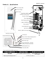
Страница 25: ...Drive Board and Drive Transformer under board Reaction Chamber Power Supply Inline Particulate Filter 4 20mA Control Board Pressure Switch Cover Safety Switch External Loop Remote 4 20mA Control Lead...

Страница 26: ...rs Drive Board and Drive Transformer XFMR under boards Inline Particulate Filter Power Supply Pressure Switch 4 20mA Control Board Cover Safety Switch External Loop Remote 4 20mA Control Leads Air Pre...

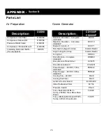
Страница 27: ...00P RCC10 Dielectric Anode 2 RCC71 Non High Voltage End Cap Contact Dealer High Voltage End Cap Contact Dealer O ring Set ORS40 Drive Module Complete CD2000P DRM60 Drive Module Transformer HVT275 Driv...

Страница 28: ...1 Filter Inline particulate filter FUS20 2 Fuse Bussmann MDL 5 5 amp 250VAC Slow Blow Main Power ORG110 4 O ring 2 CD reaction chamber pressurized end cap large ORG120 4 O ring 2 CD reaction chamber p...

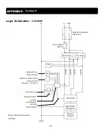
Страница 29: ...try Module With Fuses High Voltage Transformer Drive Board Remote 4 20mA Ozone Output Control Orange Purple Manual Ozone Output Control Fan Power Supply Cover Safety Switch Power Supply 4 20mA Control...

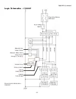
Страница 30: ...afety Switch Power Supply Power Supply Fan Fan 24VDC 24VDC 24VDC 24VDC Manual Ozone Output Control Remote 4 20mA Ozone Output Control Orange Purple External Loop 4 20mA Control Board Variable Output S...

Страница 31: ...30 Drive Module Input Voltages Shown Dual HO Drive Module APPENDIX Section E...

Страница 32: ...nced with the product and or part must be clearly described The RGA number must appear prominently on the exterior of the shipped box es The product and or part must be packaged either in its original...

Отзывы: